|
Page 14.02: Rear and Stub Spars |
|
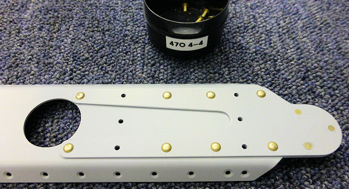
Step 01: Cleco one W-1208B Stub Spar Doubler to each of the
W-1208C-L & R Stub Spar Channels, on the outer web ( opposite the
direction that the flanges are bent ) as shown in Figure 1. Mark the
stub spar doublers as left and right per call out in Figure 1. Refer to
the stub spar doubler and channel as the Left and Right Stub Spar
Assembly
CAUTION: Avoid using a dimple as a guide for the
countersink depth. The dimple may prevent the skin from laying flat even
when the countersink is too large. |
|
|
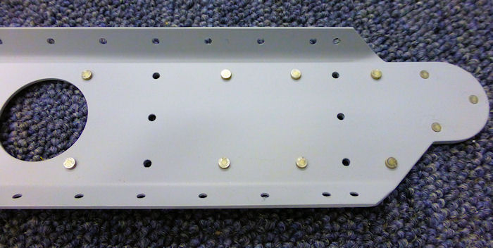
Step 02: Machine countersink 120° the W-1208C-L & R Stub Spar
Channel, per dimensions in Figure 2, on the outer surface of all the
holes in both flanges as called out in Figure 3. Drill a 1/4 inch
hole in a thin piece of scrap aluminum to make checking the maximum
diameter of each countersink easy/
|
|
| Step 03: Machine
countersink 100 deg the three holes at the inboard end of the Stub Spar
Assembly to fit the head of an AN426AD3 rivet as callout in Figure 3. |
|
Step 04A: Rivet the Stub
Spar Assembly together at the holes called out in Figure 3. Leave open the called out holes that will later
correspond to the wing ribs.
|
 |
Step 04B: When setting
the three flush rivets at the inboard end of each Stub Spar Assembly,
the goal is to make both the shop head and manufactured head as flush as
possible ( Section 5H ).
Set both Stub Spar Assemblies aside
until called for in Section 15, Wing Ribs. |
 |
| Step 05: Cleco one of
the W-1216-R Flaperon Hinge Brackets to one of the W-1216-L Flaperon
hinge Brackets as shown in Figure 4. |
|
| Step 06: Rivet the
W-1216-L & R Flaperon Hinge Brackets Together using the rivets called
out in Figure 4. Set the rivets in a random pattern to prevent warping
in the final assemblies. Refer to each of these assemblies as W-1216
Hinge Bracket Assembly. Set all four W-1216 Assemblies aside until
Section 16, Wing Skelton. |
|
| Step 07: Machine
countersink the W-1212B-L & R Flaperon Hinge Brackets per callouts in
Figure 5. |
|
| Step 08: Press one
Bearing Com-3-5 into each of the W-1212A Flaperon Hinge Plates as shown
in Figure 5. Use a 7/16", 3/8 " drive socket to back up the flaperon
hinge plate. Squeeze with a vice od a clamp. |
|
| Step 09: Cleco each of
the W-1212A Flaperon Hinge Plates between one each of the W-1212B-L & R
Flaperon Hinges. Press the area around the BEARING COM-3-5 of the
assembly together to insure that the bearing is seated into the recesses
in the flaperon hinge bracket sides and not spreading the assemblies
apart near the bearing. |
|
| Step 10: Rivet the
W-1212A Flaperon Hinge Plates and the W-1212B-L & R Flaperon Hinges
together using the rivets called out in Figure 5. Set the rivets in a
random pattern to prevent warping in the final assemblies. Refer to each
of these assemblies as the W-1212 Hinge Assembly. Set both W-1212 Hinge
Assemblies aside until later in this section. |
|
| Step 11: Mark the
W-1207C Tip Attach Angle as a left and right part per call outs in Figure
6. Separate the W-1207C-L & R Tip Attach angles by removing the joining
material shown hatched in Figure 6. |
|
|
Page 14.02: Rear and Stub Spars |
|
