
| Home | Empennage kit | Wing Kit | Fuselage Kit | Finish Kit | Power Plant Kit | Avionics | Paint | Interior | Home |
 |
|||||||||||
|
|||||||||||
| SPAR ASSEMBLY | REAR & STUB SPARS | WING RIBS | STALL WARNING | WING SKINS | FLAPERON | BUILDERS LOG |
| Page 16.02 Stall Warning |
|
|||||||||||
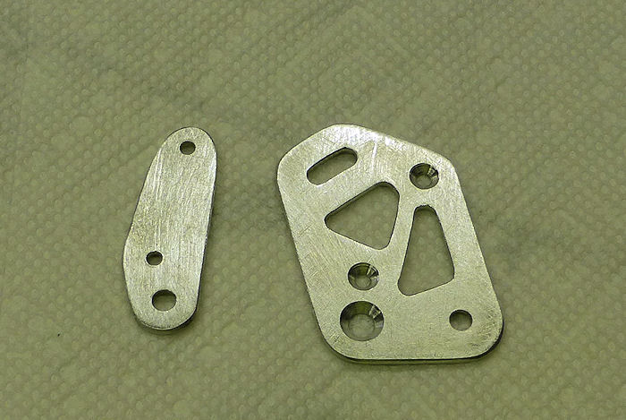
| Step 01: Final- Drill
#30 the Holes in the VA-195A Mount Plate and VA195B Keeper Plate That
are used to mount the ES E22-50K Micro Switch. Machine countersink both
holes of the mount plates inboard side for the flush head of a #4 screw
see Figure 1. Step 02:Final-Drill #19 the hole in the VA-195A Mount Plate and VA-195B Keeper Plate that holds the #8 screw on withh the VA-196 Stall Warning vane pivots Machine countersink this hole in the mount plate on the inboadr side for the fulsh head of a #8 Screw see Figure 1. Step 03: Deburr all holes and edges. Photo 06/01/15 |
 |
|||||||||||
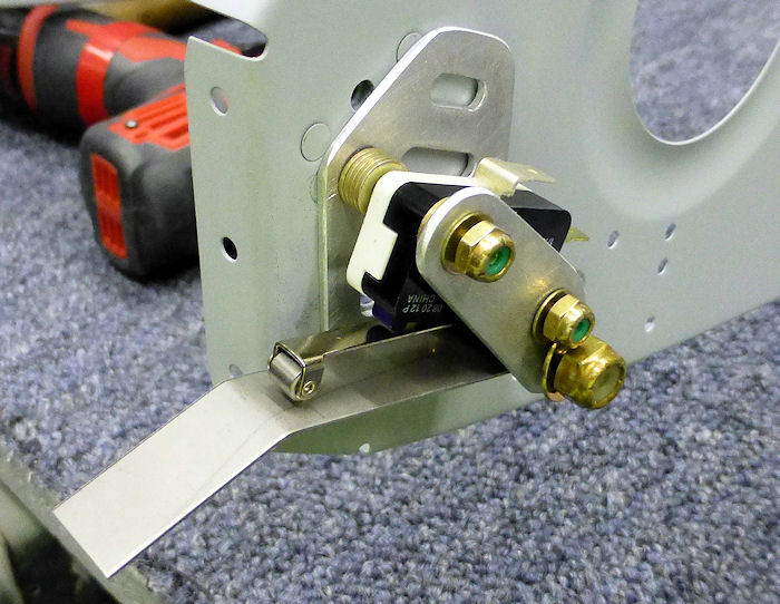
| Step 04: Assemble the
Stall Warning Subassembly as shown in Figure1. Do not over-torque the
nut on the screw about witch the VA-196 Stall warning Vane Pivots.
Insure that the stall warning vane can rotate freely. Builder Note: After installing the 24 washers of mixed types I did not like this design. |
 |
|||||||||||
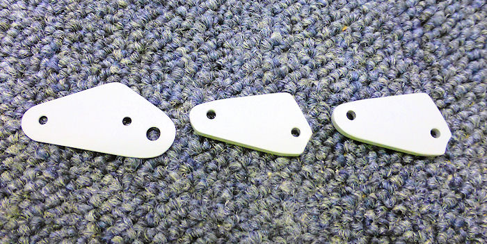
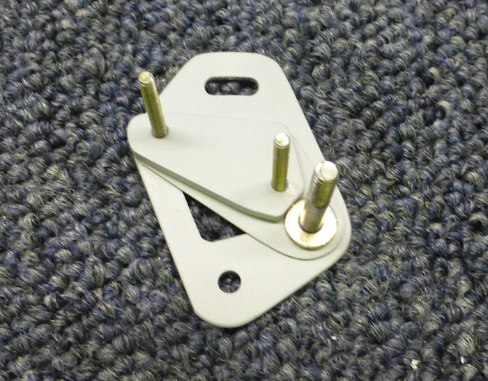
| Step 05: ( New Design )
Make three washer replacement plates. Photo 06/01/15 |
 |
|||||||||||
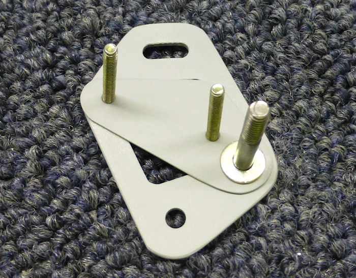
| Step 06: Install first
washer plate and one washer. Photo 06/01/15 |
 |
|||||||||||
| Step 07: Install second
washer plate and one more washer. Photo 06/01/15 |
 |
|||||||||||
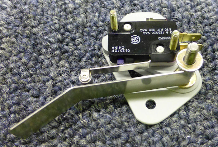
| Step 08: Install the
Micro switch, the VA-196 Stall warning Vane and one washer. Photo 06/01/15 |
 |
|||||||||||
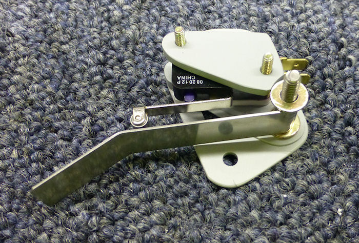
| Step 09:
Install the third washer plate. Photo 06/01/15 |
 |
|||||||||||
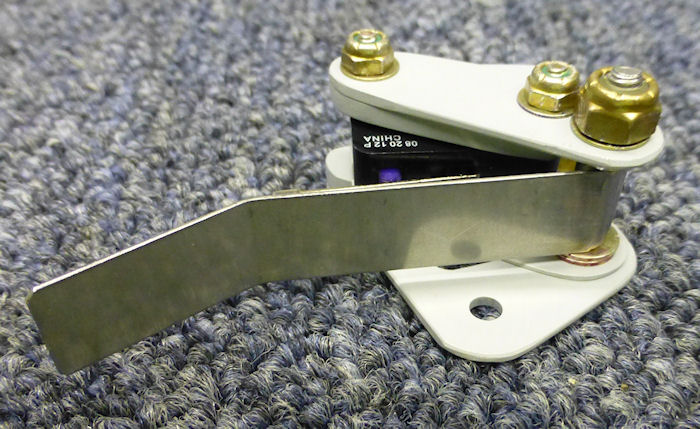
| Step 07: Install the
VA195B Keeper Plate washers and nuts. Photo 06/01/15 |
 |
|||||||||||
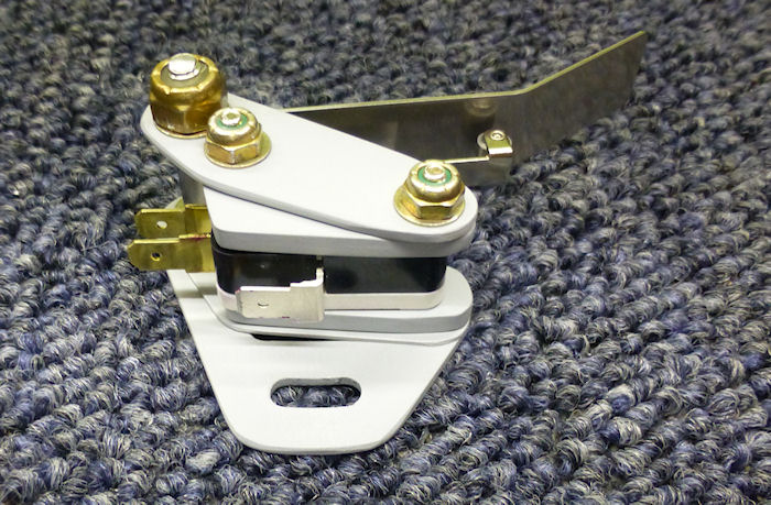
| The top View of the new
design. Photo 06/01/15 |
 |
|||||||||||
| Page 16.02 Stall Warning |
|
|
|
||||||||||
|
Disclaimer : Information contained on this Site may be out of date and /or inaccurate - Please Confirm any important data with a reliable source. |