|
Page 20.03 Center
Section Bulkhead |
|
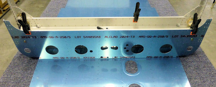
Step 01: Place F-1276 Bottom Skin
on the tabletop. Place F-1204 Center Section assembly over bottom skin
and cleco the bottom Flanges of the bulkheads as shown in Figure 1.
07/22/12 |
 |
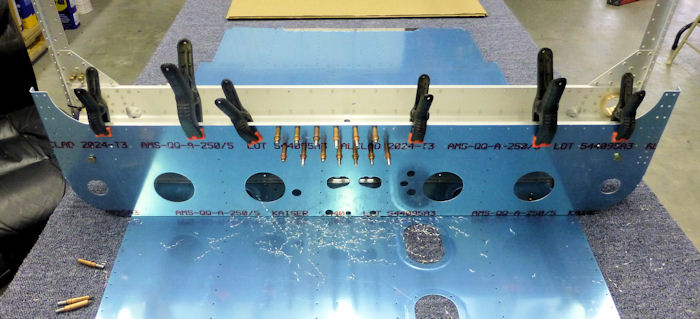
Step 02: Temporarily loosen the
clamps holding the F-1204D Center Section Aft Bulkhead to the F-1204
Center Section Assembly and allow the parts to re-line according to
their being clecoed to the F-1276 Bottom Skin. Tighten the clamps and
mach-drill #30 the holes in the center section aft bulkhead into the
center section assembly beginning at the center and progressively
drilling and clecoing outboard. See Figure 1. Drill # 11 two places, see
Pg 20-04, Figure 1.
07/22/12 |
 |
Step 03: Un-cleco the bottom
flanges from the F-1276 Bottom Skin and remove the F-1204 Center Section
Assembly and F-1204D Center Section Aft Bulkhead. Set aside the bottom
skin as it will be called for at a later stage of fuselage assembly.
Un-cleco the center section aft bulkhead from the center section
assembly, remove the AN4 bolts, and deburr all match-drilled holes.
07/22/12 |
 |
|
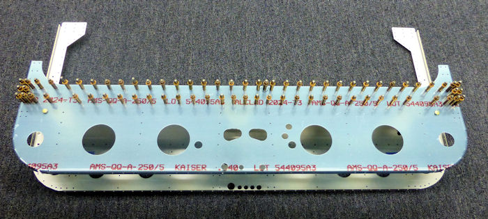
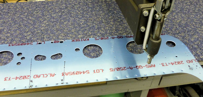
Step 04: Machine with a 100 ( deg
) Countersink the holes in the F-104 Center Section Assembly that
receive an AN426AD4 rivet, See Figure 2 and Pg 20-04 Figure 1. A piece
of thin scrap with a 1/4" hole drilled in it may be used to check the
diameter ( as described on page 14-02 ) . Dimple the corresponding holes
in the F-1204D Center Section Aft Bulkhead, See Pg 20-04 Figure 1. |
 |
|
|
 |
|
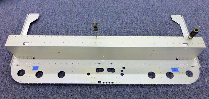
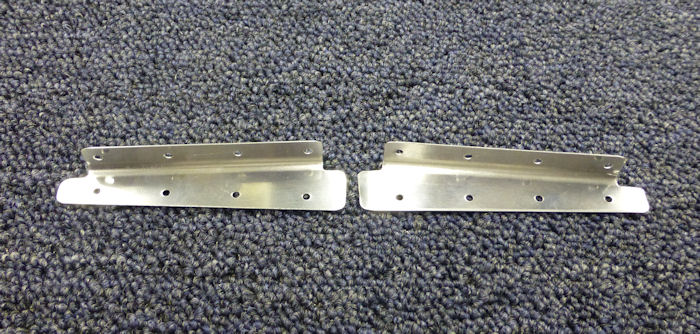
Step 05: Cut apart the F-1204P
Skin Attach Flange to make F-1204P-L and F1204P-R Skin Attach Flanges as
shown in Figure 3. |
 |
|
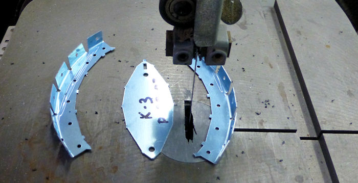
Step 06:
Separate the F-1204T-L and F-1204T-R Skin
Stiffener by removing the hatched areas shown in
Figure 4. |
 |
|
Step 07:
Separate the F-1204U-L and F-1204U-R Skin
Stiffener by removing the hatched areas shown in
Figure 5. |
|
|
Step 08:
Bend the bottom flanges of the F-12004U-L and F-1024U-R Skin Stiffners
up ( to fitthe inside radius of the F-1024 Center Section Assembly ) as
shown in figure 6. See 20-05 Figure 1 for the radius and part location. |
|
|
|
|
| |
|
|
Page 20.03 Center
Section Bulkhead |
|
|
|
