
| Home | Empennage kit | Wing Kit | Fuselage Kit | Finish Kit | Power Plant Kit | Avionics | Paint | Interior | Home |
|
|
|||||||||||
|
|||||||||||
| VERTICAL STAB | RUDDER | ANTI-SERVO TAB | STABILATOR | TAILCONE | EMP ATTACH | EMP FAIRINGS | BUILDERS LOG |
| Page 06.07 Vertical Stabilizer |
|
|||||||||||
|
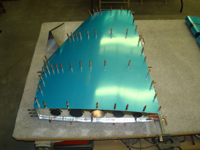
Caution: Do not force fit the VS-1201 Main
Skin. Align holes by adjusting the ribs of the V-Stab Skeleton. Step 01: Cleco the 1201 Main Skin to the V-Stab Skeleton assembly as shown in Figure 1. First cleco one side of the skin, then check that the narrow end of the VS-102 Front Spar VS-1205 Tip Rib, and VS-1205 Mid Rib will not deform the leading edge of the main skin. If any of the ribs deform the leading edge of the main skin, radius the narrow ends of the ribs ( See Page 56-05, Step 1 ). Next, check the main skin hole alignment with the ribs on the side not yet clecoed. If holes do not align, remove the skin and adjust the ribs by additional fluting or lessening flutes ( Section 5N ) until the rib holes align with the skin holes. When all of the holes align, cleco the rest of the the main skin. Builder Note: Hold for priming 07/12/10 |
 |
|||||||||||
|
STEP 01 A: ALTERATION 120° Dimple Die the VS-1201 Vertical Stabilizer Skin. T.4 09/23/10 Photo Note: Some Photos on this site will show the Alteration. |
 |
|||||||||||
|
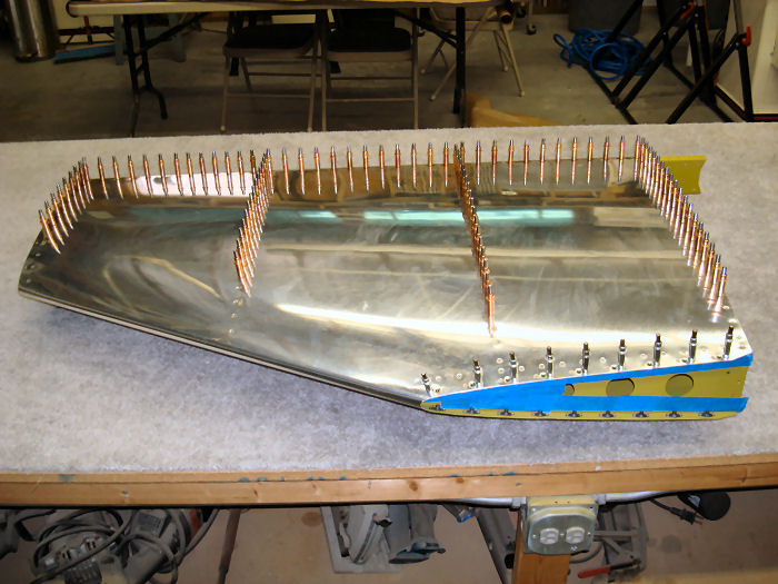
Step 02: Starting nearest
to the leading edge of the VS-1201 Main Skin. remove one cleco and rivet
that hole before moving on to the next hole. Continue
until all of the main skin holes are riveted to the corresponding holes
in the V-Stab Skeleton Assembly per call-out in Figure 1. 09/27/10 |
 |
|||||||||||
|
Step 03: Rivet the
remaining open holes of the flange at the lower end of the V-Stab
Skeleton Assembly per call-out in Figure 1. This is now the Vertical Stabilizer Builder Note: Alteration Rivets Used 09/29/10 |
 |
|||||||||||
| Step 04: Screw the VS-1204 Fwd Skin to the nutplates at the front of the V-Stab Assembly using the hardware called-out in Figure 1. The bottom eight holes in the fwd skin are left open until the V-Stab Assembly is installed to the Tailcone Assembly. | This Step on Hold until Section 11 page 09 Step 01 | |||||||||||
|
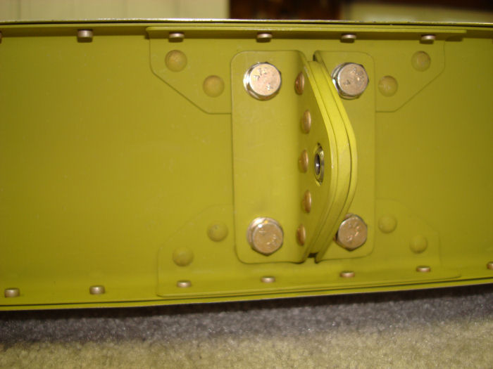
Step 05:
Bolt the Upper Hinge Assembly to the V-Stab Assembly using the hardware
called out in Figure 1. 09/29/10 |
 |
|||||||||||
|
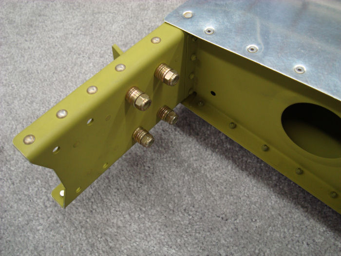
Step 06:
Tie The Lower Hinge Assembly to the V-Stab Assembly through the bolt
holes that will be used to attach the Lower Hinge Assembly and tape a
bag of the hinge hardware to the tie. The Lower Hinge Assembly will be
installed when the V-Stab Assembly is installed to the Tailcone
Assembly. NOTE: The Vertical Stabilizer fairing installation instructions are included in Section 12: Emp Fairings. Builder Note: Skip Step 06 See Section 07 Page 03 Step 01 From Section 07 Step 01: Check the rudder hinge alignment by temporarily attaching the Lower Hinge Assembly to the V-Stab Assembly Washer added to prevent the bolt from reaching nylon in nuts. |
 |
|||||||||||
| Builder Note: | Read and preview all assembly steps prior to Construction | |||||||||||
| Page 06.07 Vertical Stabilizer |
|
| VERTICAL STAB | RUDDER | ANTI-SERVO TAB | STABILATOR | TAILCONE | EMP ATTACH | EMP FAIRINGS | BUILDERS LOG |
|
||||||||||
|
Disclaimer : Information contained on this Site may be out of date and /or inaccurate - Please Confirm any important data with a reliable source. |