
| Home | Empennage kit | Wing Kit | Fuselage Kit | Finish Kit | Power Plant Kit | Avionics | Paint | Interior | Home |
 |
|||||||||||
|
|||||||||||
| VERTICAL STAB | RUDDER | ANTI-SERVO TAB | STABILATOR | TAILCONE | EMP ATTACH | EMP FAIRINGS | BUILDERS LOG |
| Page 08.02 Anti-Servo Tab |
|
|||||||||||
| Step 01: Read all steps prior to construction. | NOTE: This section describes the Anti-Servo Tab ( AST ) construction for the left side. Construction for the right side is a mirror of the left, and should be done at the same time. | |||||||||||
|
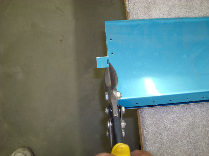
Step 02: Remove the
material shown hatched from the bottom half of the 1221_L AST Skin as
shown in Figure 1. NOTE: The top surface and inboard end of the FS-1221L AST Skin can be identified by the AST Control Horn cutout, called out in Figure 4. 07/21/10 |
 |
|||||||||||
|
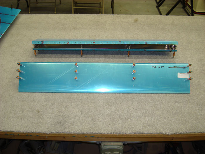
Step 03: Cleco the top and
bottom flanges of the four HS-122 AST Ribs to the inside of the
HS-1221-L AST Skin. Orient the flanges of the three inboard ribs to
point outboard. Orient the flanges of the outboard rib to point inboard
as shown in Figure 2. 07/21/10 |
 |
|||||||||||
|
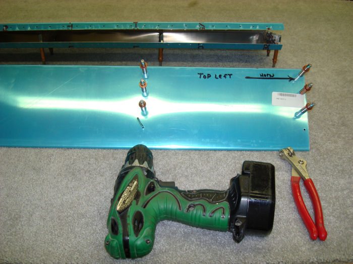
Step 04: Final-Drill #30
the HS-122 AST Ribs using the holes in the HS-122-L AST Skin nearest to
the trailing edge as a guide. Mark the rib locations to return them to
the same position as drilled for final assemblt. Disassemble, deburr holes and remove any chips. Builder Note: Hold for Priming 07/21/10 |
 |
|||||||||||
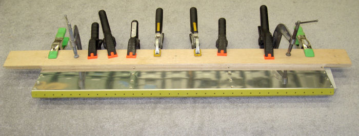
| Builder Note: Added
Step Step 04-02:Pinch the trailing edge 10/11/10 |
 |
|||||||||||
|
Step 05:
Rivet only the top flange of the four HS-122 AST Ribs inside the top
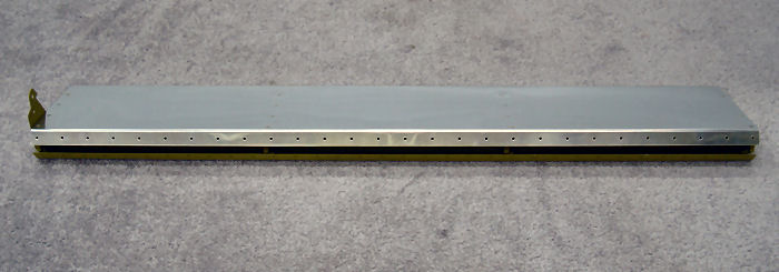
surface of the HS1221-L AST Skin per rivet call-outs in Figure 4. 10/11/10 Alteration Rivets Used Builders Note: Primed AST Parts 10/07/10 Preformed step: 08-03-03 First |
 |
|||||||||||
| Page 08.02 Anti-Servo Tab |
|
| VERTICAL STAB | RUDDER | ANTI-SERVO TAB | STABILATOR | TAILCONE | EMP ATTACH | EMP FAIRINGS | BUILDERS LOG |
|
||||||||||
|
Disclaimer : Information contained on this Site may be out of date and /or inaccurate - Please Confirm any important data with a reliable source. |