
| Home | Empennage kit | Wing Kit | Fuselage Kit | Finish Kit | Power Plant Kit | Avionics | Paint | Interior | Home |
|
|
|||||||||||
|
|||||||||||
| VERTICAL STAB | RUDDER | ANTI-SERVO TAB | STABILATOR | TAILCONE | EMP ATTACH | EMP FAIRINGS | BUILDERS LOG |
| Page 08.03 Anti-Servo Tab |
|
|||||||||||
|
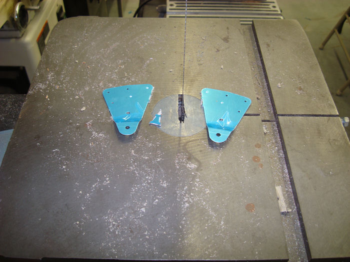
Step 01:
Mark and separate the F-11220-L&R AST Control horns per call-outs in
Figure 1. 07/21/10 |
 |
|||||||||||
|
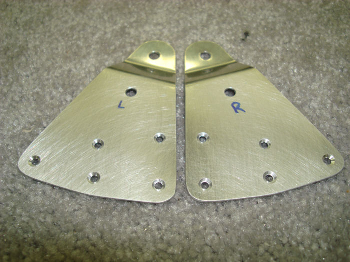
Step 02: Machine
countersink the HS 12200-L&R AST Control Horns for a 3/32" rivet per
call-out in Figure 2. 07/21/10 |
 |
|||||||||||
|
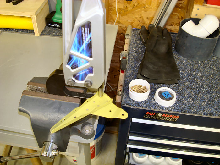
Step 03: Orient the AST
Control Horn to pass through the AST control horn cut-out. Rivet The
HS-1220-L AST Control Horn to the inboard DS-122 AST Rib as shown in
Figure 2. 10/11/10 Alteration Rivets Used Builder Note: Primed AST Parts 10/07/10 Step out of sequence |
 |
|||||||||||
|
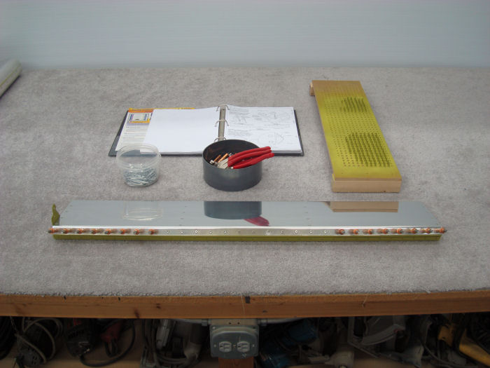
CAUTION: Rivet only the upper flange of the
skin to the spar at this time Per step 4. Step 04: The HS-1219-L AST Spar must be installed on the inside surface of the HS-122L AST Skin as shown in Figure 4. The reference hole in the AST spar, shown in Figure 3, must be oriented up and outboard. Rivet the AST Spar to the AST Skin per call-out in Figure 4, Omit the reference hole when riveting. 10/11/10 Builder Note: LP4-3 Used in this step. |
 |
|||||||||||
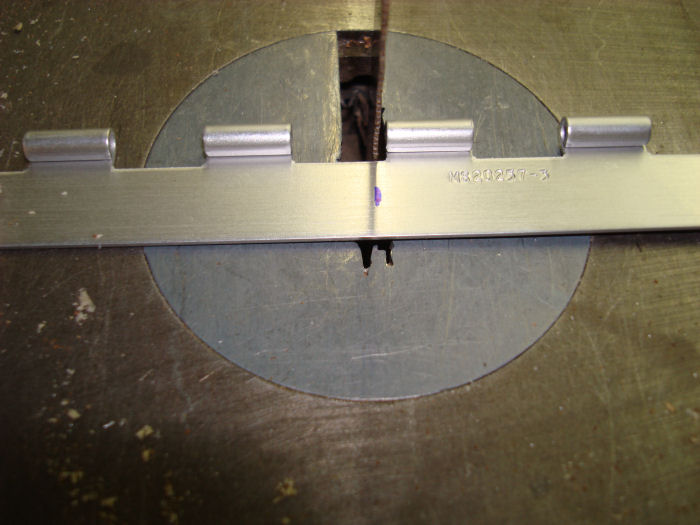
| Step 05:
Remove the hinge pin from one AN275-P3X6 ( also known as MS20257-3 )
Piano Hinge. Cut each of hinge halves into two lengths per dimensions
given in Figure 5. Locate cuts so that there are hinge eyelets at both ends of all four hinge halves. Two hinge half lengths will be the left and right HS-128B AST Hinges. The other two lengths will be left and right HS-1238A AFT Stab Hinges. The aft stab hinges will be installed in Section 9. Stabilator Assembly. The hinge pins will be installed in Section 11. Empennage Attach. NOTE: Save the HS-1223 Drill Guide for use in Section 9. 07/21/10 |
 |
|||||||||||
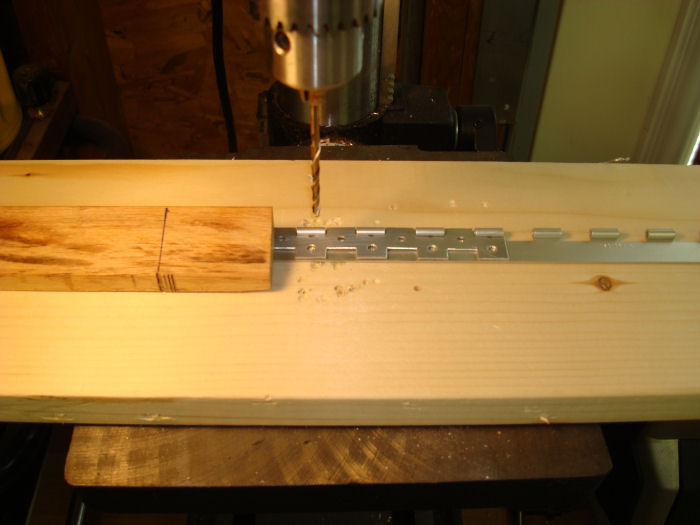
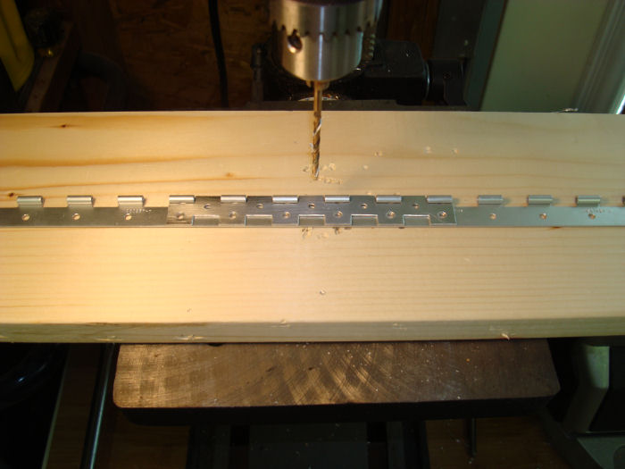
| Step 06:
Position the HS-1223 Drill Guide per Figure 6, Detail A. Orient the
notched edges of the drill guide adjacent to the eyelets of the hinge
half, then clamp the drill guide onto the AST hinge half. 07/21/10 |
 |
|||||||||||
| Step 07: Match-Drill #30 the Hinge Half, using the DS-1223 Drill
Guide per Figure 7, Refer to Figure 6, Detail B to remove the drill
guide. Repeat Step 6 and 7 until the entire hinge half has been drilled
to make the HS-1218B AST Hinge Half. Builder Note: Hold for Priming 07/21/10 |
 |
|||||||||||
| Page 08.03 Anti-Servo Tab |
|
| VERTICAL STAB | RUDDER | ANTI-SERVO TAB | STABILATOR | TAILCONE | EMP ATTACH | EMP FAIRINGS | BUILDERS LOG |
|
||||||||||
|
Disclaimer : Information contained on this Site may be out of date and /or inaccurate - Please Confirm any important data with a reliable source. |