|
Page 24.02 Rollover
Structure & F-1207 Bulkhead
|
|
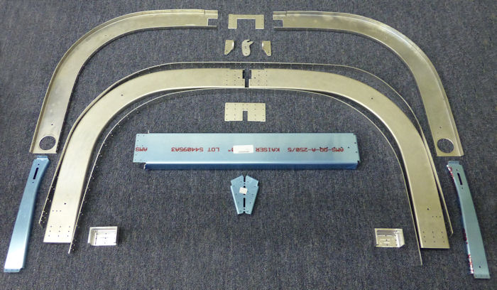
| Step 01: Study Figure 1
to determine the forward edge, top and bottom of the F-1231B & C Roll
Bar Straps. Run the roll bar straps back and forth over the table to add
curvature to the parts. Be careful not to let the parts kink across the
rivet holes. The curve does not have to be the final installed shape but
enough to allow easy assembly to the roll bar. Deburr the edges of all
parts used to create the Roll Bar Assembly. Cleco all the parts of the
Roll Bar Assembly Together as shown in Figure 1. |
Alteration
This rollover structure
is also covered in alteration
04 Canopy lock & 07 Rear
Window |
| Step 02: Final-Drill
#30 all #40 holes in the flanges of the F1231A-FL, FR, AL & AR Roll Bar
Frames and F123B & C Roll Bar Straps. |
|
Step 03: Disassemble
the roll bar parts, then machine countersink the other flanges of the
F1231A-FL, FR , AL and AR Roll Bar Frames for the head of the rivets
that will lay underneath the canopy except holes common to the F1231D
Roll Bar Bases. Machine countersink the two holes on the inside lower
center face of the roll bar that will get flush blind rivets. See Figure
1.
Caution: Do not rivet the locations marked with a triangle in
figure 1 at this time. |
 |
| Step 04: Rivet the
F1231F Latch Plate to the F123A-AR Roll Bar Frame and aft F-123E Splice
Plate as shown in Figure 1. |
|
| Step 05: Rivet the
F-1231A-FL, AL & AR Roll Bar Frames to the F-1231B & C Roll Bar Straps
and F123E Splice Plates per the callouts in Figure 1 to create the Roll
Bar Assembly. |
|
| Step 06: Remove the
hatched areas shown in Figure 2 from the flanges of both the F-1254-L &
R Support Frames. |
|
| Step 07: Deburr then
dimple both holes indicated in Figure 2 for the head of a #8 screw. |
|
| Step 08: Remove the
hatched areas shown in Figure # to separate the F-1232B Roll Bar
Brackets into left and right parts. |
|
|
Page 24.02 Rollover
Structure & F-1207 Bulkhead
|
|
