|
Page 27.02 Rudder Pedals
& Brake System
|
|
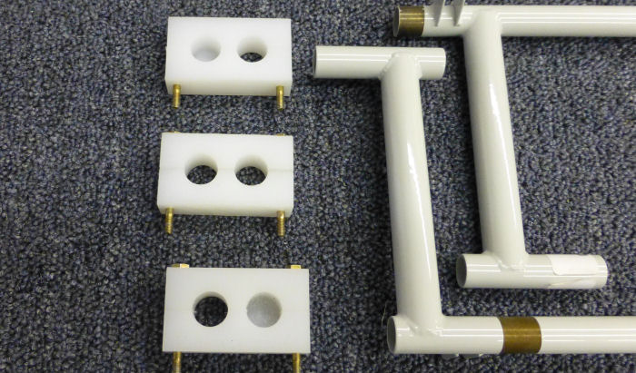
Step 01: Split the
F-1235A Inbd Rudder Pedal Block and the two F-1235B Outbd Rudder Pedal
Blocks shown in Figure 1. Mark the split parts so that they remain
together and in there original pre-split orientation.
11/11/12
Builder Note: Bolt added to remain together. |
 |
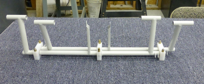
Step 02: Clamp the
WD-1206 Rudder Pedals using the F-123A & B Rudder Pedal Blocks as shown
in Figure 2. Be sure the rudder pedals are oriented as shown in the
figure ( long end and short end together ), and place the heads of the
bolts on the bottom so that the clamped assembly will lay flat on the
work surface.
11/11/12 |
 |
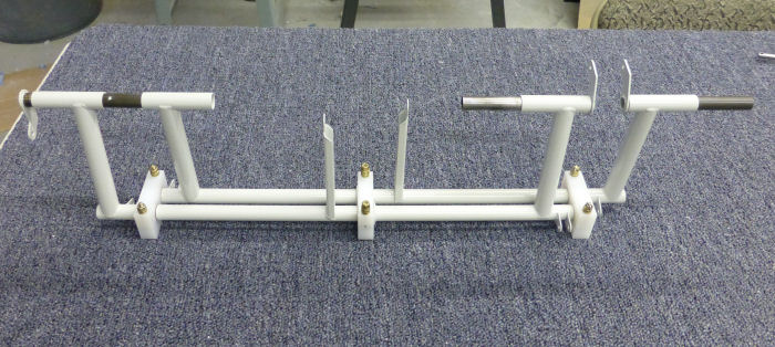
Step 03: Slide the
WD-1211-L & R Brake Pedal Torque Tubes into the WD-1206 Rudder Pedals as
shown in Figure 3.
Step 04: Be sure that
the F-1235A & B Rudder Pedal Blocks are all flush against the work
surface ( Clamp down if necessary ), then slide one of the remaining
WD-1211-L or R brake Pedal Torque Tubes ( doesn't matter witch one )
into both of the WD-1206 Rudder Pedals as shown in Figure 3. This will
lock both rudder pedals into the neutral position.
11/11/12
|
 |
Step 05: Temporarily
attach the Brake Master Cylinder - Right and Left to the WD-1206 Rudder
Pedals and WD-1211-R & L Brake Pedal Torque Tubes as shown in Figure 4.
The hardware shown in Figure 4 is called out on page 27-03 Figure 3.
11/11/12 |
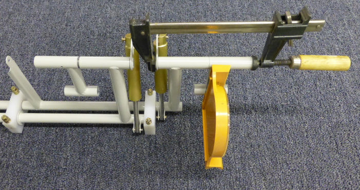 |
Step 06: Slide the
WD-1209 Brake Pedals over the WD-1211-R & L Brake Pedal Torque Tubes and
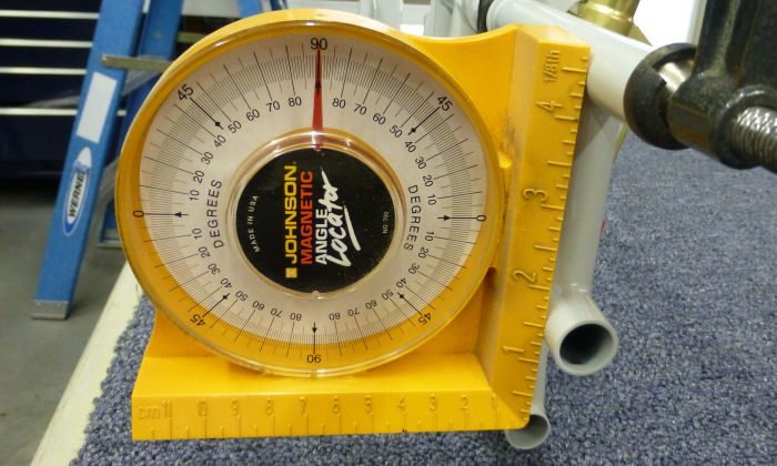
against the WD1206 Brake Pedals as shown in Figure 4. Use a square to
make sure the brake pedals are vertical and perpendicular to the work
surface, then clamp the brake pedals to the rudder pedals as shown.
11/11/12 |
 |
| |
|


