
| Home | Empennage kit | Wing Kit | Fuselage Kit | Finish Kit | Power Plant Kit | Avionics | Paint | Interior | Home |
|
|
|||||||||||
|
|||||||||||
| VERTICAL STAB | RUDDER | ANTI-SERVO TAB | STABILATOR | TAILCONE | EMP ATTACH | EMP FAIRINGS | BUILDERS LOG |
| Page 07.02 Rudder |
|
|||||||||||
| Step 01: Read all steps prior to construction. | ||||||||||||
|
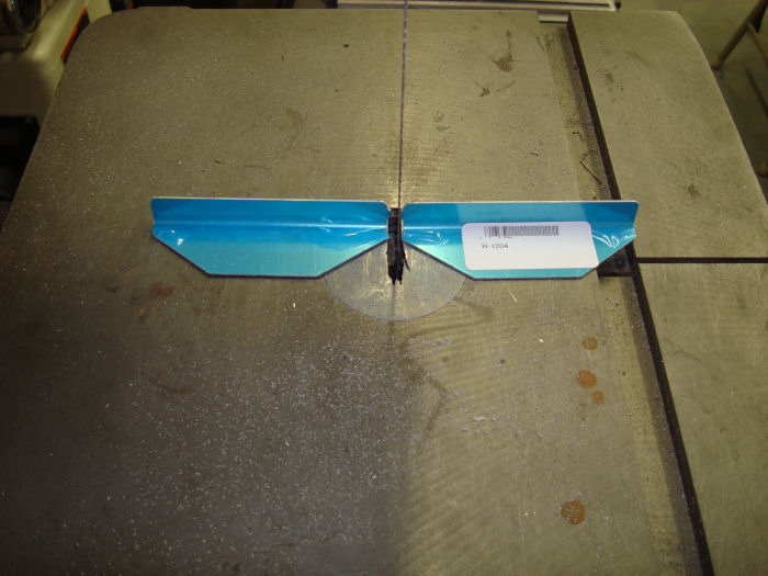
Step 02: Separate the
R-1204 Spar Caps by removing the material shown hatched in Figure 1. Deburr all the edges of both spar caps 07/12/10 |
 |
|||||||||||
|
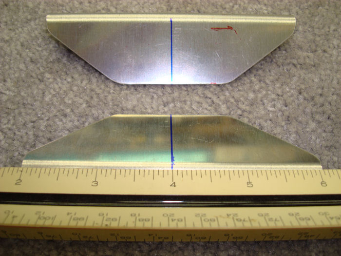
Step 03: Mark both of the
R-1204 Spar Caps with a centerline on the surface that will nest against
the R-1202 Spar web as shown in Figure 3. 07/12/10 |
 |
|||||||||||
|
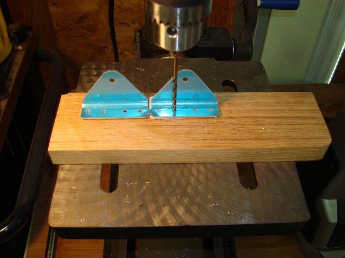
Step 04: Final-Drill #30
the 1/8" holes in the R-1205 Hinge Brackets called out in Figure 2. 07/17/10 |
 |
|||||||||||
|
Step 05:
Final-Drill #12 the 3/16" holes in the R1205 Hinge Brackets as called
out in Figure 2. 07/17/10 |
 |
|||||||||||
|
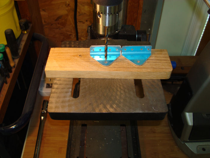
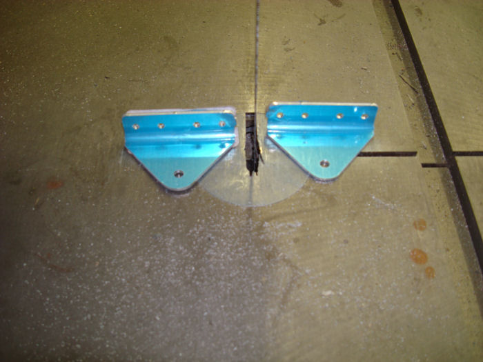
Step 06:
Separate the R-1205 Hinge brackets by removing the material shown
hatched in Figure 2. Deburr all the edges and drilled holes of both hinge Brackets. 07/17/10 |
 |
|||||||||||
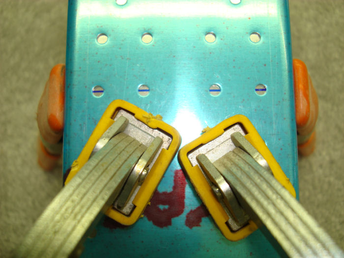
| Step 07: Position the R-1204 Spar Caps between the flanges of the
R-1202 Spar so the Centerline show through the middle set of holes in
the spar web as shown in Figure 3. Adjust the bend of each spar cap, as
necessary, to nest against the inner surfaces of the spar web and flange
as shown in Figure 3, Detail A-A Clamp the spar caps in place. Mark the spar caps left and right so they can be installed in the same position as drilled. 07/17/10 |
 |
|||||||||||
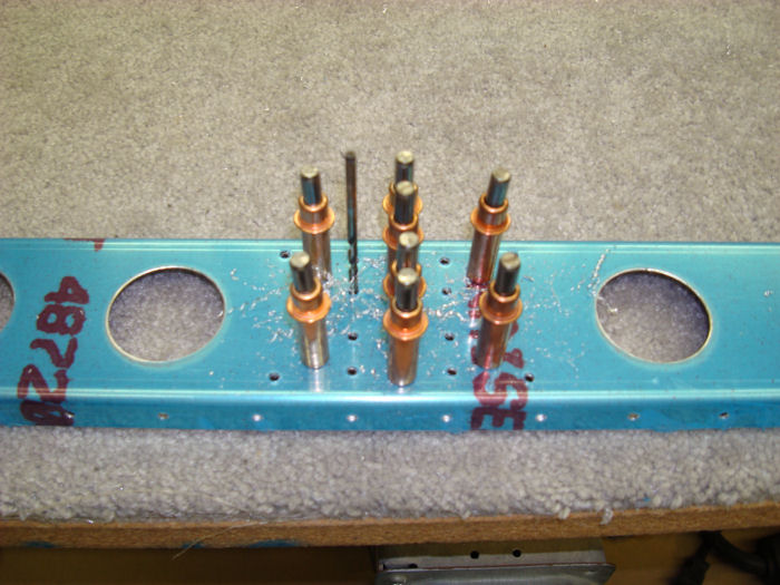
| Step 08: Match-Drill #30 the holes from the R-1202 Spar into the
R1204 Spar Caps per call-out in Figure 3. Cleco each
hole before drilling the next. First match-drill the holes in the spar
web, unclamp and clear away any chips, cleco the spar caps back in
place. 07/17/10 |
 |
|||||||||||
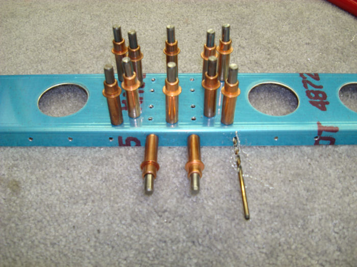
| Step 08B: Then match-drill the holes in the spar flanges. Remove the spar caps, deburr all drilled holes, and clear away any chips. 07/17/10 |
 |
|||||||||||
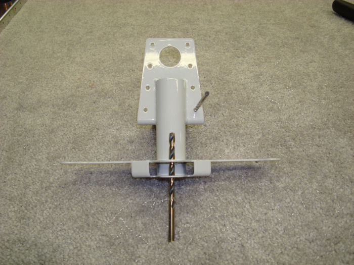
| Step 09:
Final-Drill the holes in the WD-1205 Rudder horn as shown in Figure 4. 07/17/10 |
 |
|||||||||||
| Step 09A: ALTERATION
Machine with a 110° Countersink The flanges of the R1204 Rear Spar 110° Dimple Die the R-1201 Main Skin and the Flanges of the R1203 Rudder Ribs. .5 hr. 10/05/10 |
 |
|||||||||||
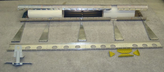
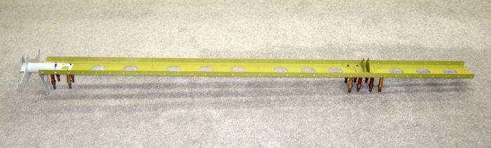
| Step 10:
Cleco the R-1204 Spar Caps, the R1205 Hinge Brackets and the Wd-1205
Rudder Horn to the R-1202 Spar. Position clecos on the web of the spar
as shown in figure 4. Hereafter refer to this assembly as the Rudder
Spar Assembly. 10/08/10 |
 |
|||||||||||
| Page 07.02 Rudder |
|
| VERTICAL STAB | RUDDER | ANTI-SERVO TAB | STABILATOR | TAILCONE | EMP ATTACH | EMP FAIRINGS | BUILDERS LOG |
|
||||||||||
|
Disclaimer : Information contained on this Site may be out of date and /or inaccurate - Please Confirm any important data with a reliable source. |