| Home | Empennage kit | Wing Kit | Fuselage Kit | Finish Kit | Power Plant Kit | Avionics | Paint | Interior | Home |
 |
|||||||||||
|
|||||||||||
| VERTICAL STAB | RUDDER | ANTI-SERVO TAB | STABILATOR | TAILCONE | EMP ATTACH | EMP FAIRINGS | BUILDERS LOG |
| Page 07.04 Rudder |
|
|||||||||||
|
Step 01:
Rivet the R-1203A Trimmed Rib to the WD-1205 Rudder Horn. Flange
orientation and rivet call-outs are shown in Figure 1. Refer to this
assembly as the Rudder Horn Assembly. 10/08/10 Builder Note: Alteration Rivets Used |
 |
|||||||||||
|
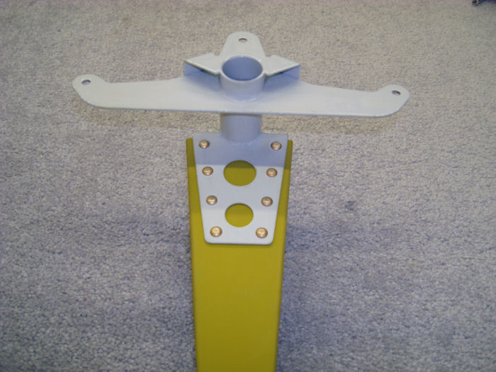
Step 02:
Rivet the Rudder Horn Assembly to the to the R-1202 Spar, as shown in
Figure 2. 10/08/10 |
 |
|||||||||||
|
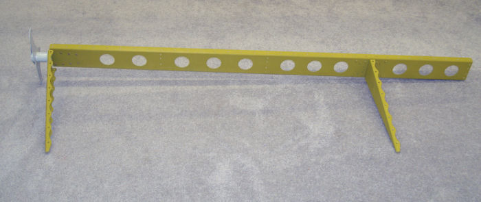
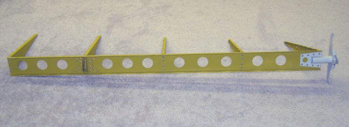
Step 03: Rivet the three
remaining R-1203 Main Ribs to the R1202 Spar. Flange orientations and
rivet call-outs are shown in Figure 3. Refer to this assembly as the
Rudder Skeleton Assembly. 10/08/10 |
 |
|||||||||||
| Page 07.04 Rudder |
|
| VERTICAL STAB | RUDDER | ANTI-SERVO TAB | STABILATOR | TAILCONE | EMP ATTACH | EMP FAIRINGS | BUILDERS LOG |
|
||||||||||
|
Disclaimer : Information contained on this Site may be out of date and /or inaccurate - Please Confirm any important data with a reliable source. |