| Home | Empennage kit | Wing Kit | Fuselage Kit | Finish Kit | Power Plant Kit | Avionics | Paint | Interior | Home |
 |
|||||||||||
|
|||||||||||
| VERTICAL STAB | RUDDER | ANTI-SERVO TAB | STABILATOR | TAILCONE | EMP ATTACH | EMP FAIRINGS | BUILDERS LOG |
| Page 07.03 Rudder |
|
|||||||||||
|
Step 01:
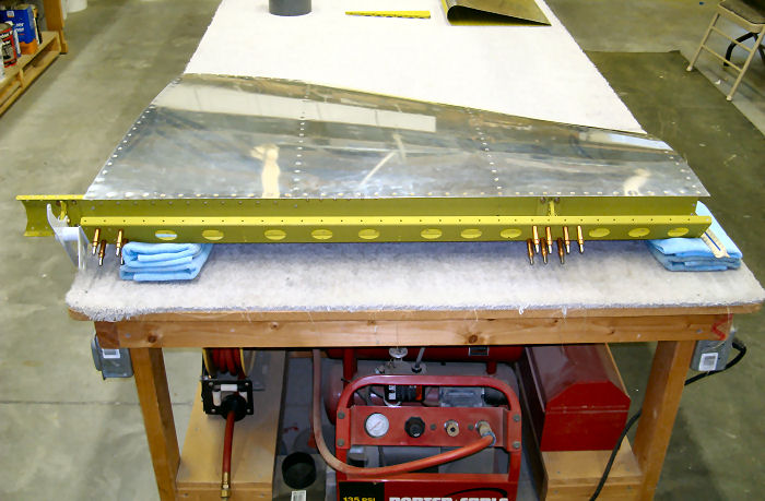
Check the rudder hinge alignment by temporarily attaching the Lower
Hinge Assembly to the V-Stab Assembly. Temporarily attach the Rudder
Spar Assembly to the V-Stab Assembly as shown in Figure 5. When installing the hinge hardware, use one washer between the bolt head and R-1205 Hinge Bracket, one Washer between nut and hinge bracket, and only one washer between each hinge bracket and upper hinge assembly. AN960-10L Washers may be substituted for AN960-10 Washers to adjust Clearance between hinge brackets. Once a fit is confirmed, make note of the washers used. Detach the Rudder Spar Assembly. 10/08/10 |
 |
|||||||||||
|
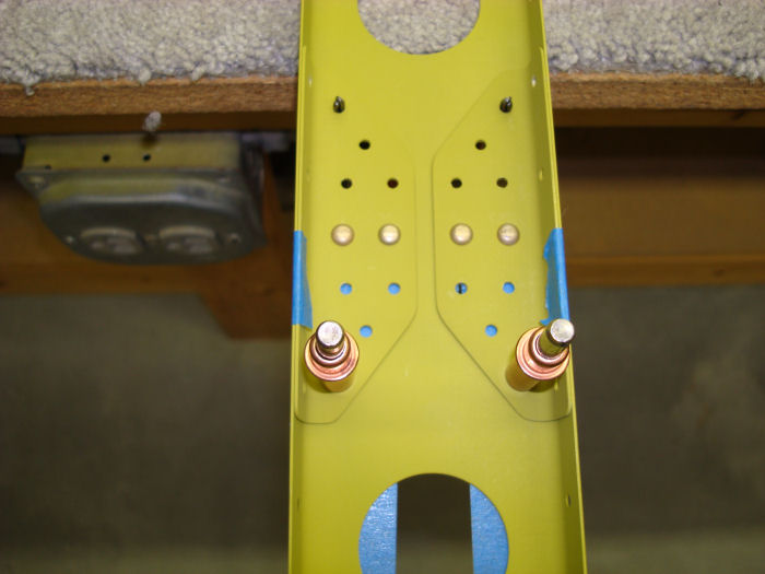
Step 02: Remove the R-1205
Hinge Brackets and WD-1205 Rudder Horn. Rivet the R-1204 Spar Caps and
the R1203 Main Rib to the R1202 Spar. Rivet only the four holes common
to the main rib. See the call-out in Figure 2. 10/08/10 Builders Note: Blue painters tape used to prevent tools from scratching new paint Alteration Rivets Used |
 |
|||||||||||
|
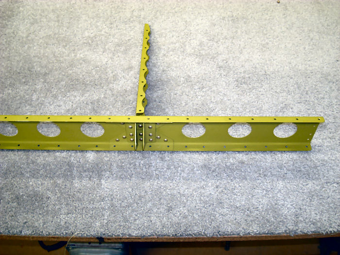
Step 03: Rivet the R-1205
Hinge Brackets to the R-1204 Spar Caps and R-1202 Spar. Rivet the
remaining holes in the spar caps to the Spar, See the rivet call-outs in
Figure 2. 10/08/10 |
 |
|||||||||||
|
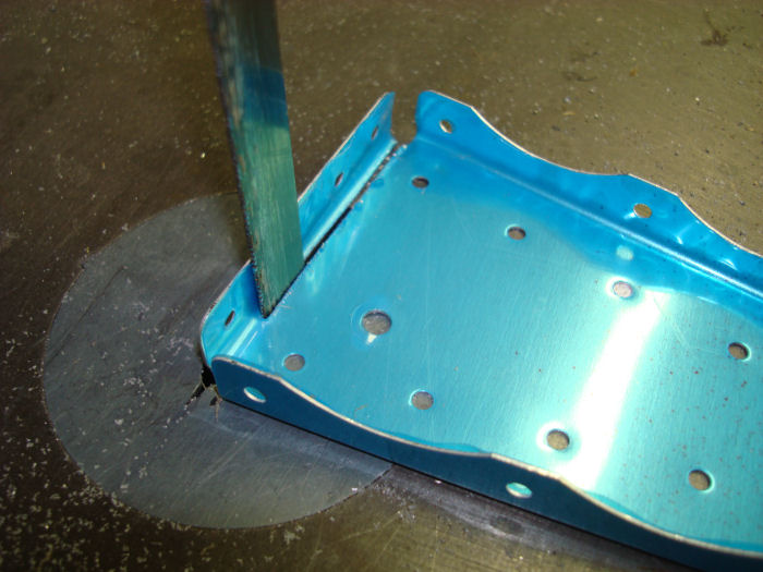
Step 04: Remove the
forward flange from one R-1203 Main Rib, per dimension in Figure 3.
Deburr The trimmed edge. Hereafter refer refer to this as R-1203A
Trimmed Rib. 07/17/10 |
 |
|||||||||||
| Page 07.03 Rudder |
|
| VERTICAL STAB | RUDDER | ANTI-SERVO TAB | STABILATOR | TAILCONE | EMP ATTACH | EMP FAIRINGS | BUILDERS LOG |
|
||||||||||
|
Disclaimer : Information contained on this Site may be out of date and /or inaccurate - Please Confirm any important data with a reliable source. |