|
Page 22.02 Fwd Lower
Fuselage
|
|
|
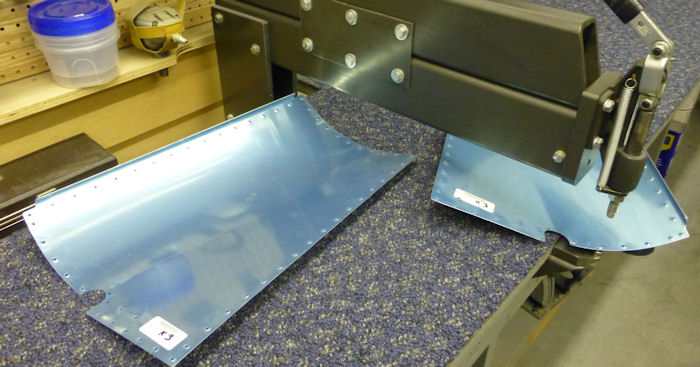
Step 01: Dimple the #40 holes in
the nutplate attach pattern labeled " Return Line Clamp" on the
F-1201C Firewall Bottom, flush aft side. See Figure 4. |
|
| Step 02:
Machine countersink the nutplate attach holes in the sloped upper flange
of the F-1217A-L & R Tunnel Ribs as shown in Figure 1. Machine
countersink all the nutplate attach holes in the F-1272 Fwd Fuse Skin
flush on the bottom side. See Figure 4. Machine countersink the upper
most hole in the F-1288 Cooller Stiffener. See Figure 1. |
|
Step 02B: Dimple all the holes in the F1272 L & R Fwd Fuse Corner
Skin
Builder Note:
Alteration 01 |
 |
| Step 03:
Rivet nutplates to the F-1217A-L & R Tunnel Ribs and F-1201C Firewall
Bottom per the callouts in Figure 1 and Figure 4. |
|
| Step 04:
Cleco, final-drill #30, the WD-1204 Engine Mount Brackets to the
F-1217A-L & R Tunnel Ribs as shown in Figure 1. Rivet the engine mount
brackets to the web of the tunnel ribs ( not the fwd flange, installed
from the bottom side ). |
|
| Step 05:
Machine countersink #30 the holes in the forward flange of the F-1217A-L
and R Tunnel Ribs that correspond to the flush rivets called out in
Figure 4. |
|
| Step 06:
Cleco then rivet, the F-1217A-L & R Tunnel Ribs to the F-1272 Fwd Fuse
Skin ( Do Not Rivet the aft most hole! ). To this assembly cleco then
rivet the F-1201C Firewall Bottom & F-1271-L & R Fwd Fuse Corner Skin to
create the Fwd Lower Fuse Assembly ( Do Not Rivet the locations labeled
" Do Not Rivet " in Figure 1. |
|
| Step 07:
Trim the flange of the F-1288 Cooler Stiffener as shown in Figure 2. |
|
| Step 08:
Rivet the F-1288 Cooler Stiffener and corresponding nutplates to the
firewall bottom. See Figure 1 and Figure 4. |
|
| Step 09:
Rivet nutplates to theF-1217A-L & R Tunnel Ribs and F-1272 Fwd Fuse Skin
per the call outs in Figure 4. Rivet nutplates to the F-1201C Firewall
Bottom and fwd fuse skin per the call outs in Figure 4. |
|
Step 10:
Make two F-1201U Firewall Spacers from AS3-020 as shown in Figure 3.
Note: Curve parts slightly by hand in the following steps for a
better fit. |
|
| Step 11:
Center the F-1201U Firewall Spacers about the holes used to attach them
to the Fwd Lower Fuse Assembly. Place the F-1218 Cowl Attach Plates over
the top of the firewall spacer then cleco the hole on the inboard edge
of the cowl attach plates. Clamp the outboard edge of the cowl attach
plate and the firewall spacer to the Fwd Lower Fuse Assembly. See the
exploded detail view in Figure 4. |
|
| Step 12:
Match-Drill #30 the holes in the Fwd Lower Fuse Assembly into the
F-1201U Firewall Spacers and F-12118 Cowl Attach Plates. Remove and
deburr the firewall spacers. Machine countersink the nutplate attach
holes in the cowl attach plates ( flush bottom side ). Rivet nutplates
to the cowl attach plates. Rivet the firewall spacers and cowl attach
plates to the fwd lower fuse assembly. See the detail view in Figure 4. |
|
| Step 13:
Rivet a nutplate to the forward side of the F-1201C Firewall Bottom to
the location labeled "Return Line Clamp" See Figure 4. |
|
| Step 14:
Use a unibit to enlarge the hole between the gascolator attach holes per
the dimension given in Figure 4. to keep the hole centered draw a cross
hair out from the hole for reference. |
|
| |
|


