
| Home | Empennage kit | Wing Kit | Fuselage Kit | Finish Kit | Power Plant Kit | Avionics | Paint | Interior | Home |
|
|
|||||||||||
|
|||||||||||
| SPAR ASSEMBLY | REAR & STUB SPARS | WING RIBS | STALL WARNING | WING SKINS | FLAPERON | BUILDERS LOG |
| Page 15.04 Wing Ribs |
|
|||||||||||
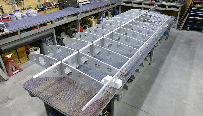
| To insure that all
countersinks and dimples needed to flush rivet the skins are complete
and to make the riveting prosses easy start with the left wing ribes all clecoed in place. Photo 05/29/15 |
 |
|||||||||||
| Step 01: Rivet one of
the W-1210-R Main Ribs to furthest outboard angle on the W-1206-L Spar,
this is now known as Main Rib-L01 Photo 05/29/15 |
 |
|||||||||||
| Step 02: Rivet one of
the W-1210-R Main Rib that is match drilled for the W-1216B-L hinge to
the next inboard angle, this is now known as Main Rib-L02 Photo 05/29/15 |
 |
|||||||||||
| Step 03: Rivet th next
four W-1210-R Main Ribs to the next inboard angles, these are now known
as Main Ribs-L03, 04, 05 and 06 Photo 05/29/15 |
 |
|||||||||||
| Step 04: River the
reamining W-1201-R Main Rib that is match drilled for the W-1216B-L
hinge to the next inboard angle, this is now known as Main Rib-L07 Photo 05/29/15 |
 |
|||||||||||
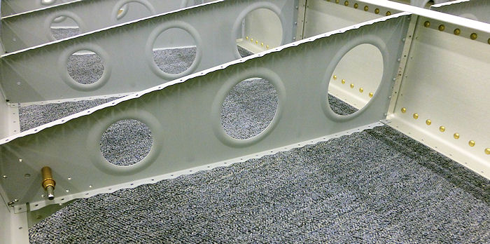
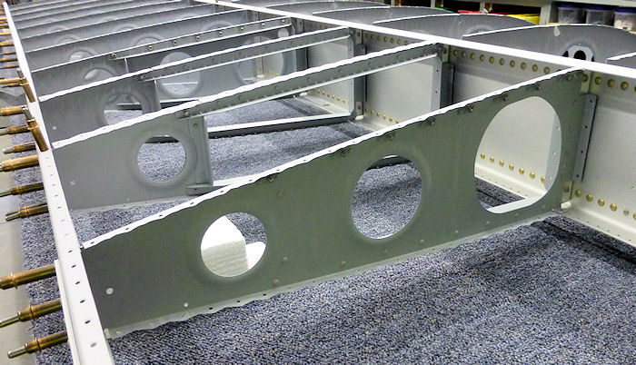
| Step 05: Rivet the
modified Outboard Tank Rib to the next inboard angle, this is now known
as Main Rib-L08-OT Builder Note: The top angle is removable for fuel tank install. The hole at the top front corner is for the fuel tank vent system. |
 |
|||||||||||
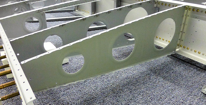
| Step 06: Rivet one of
the modified Center Tank Rib to the next inboard angle, this is now
known as Main Rib-L09-CT Builder Note: The two center left tank ribs are the same, the support angles are the inboard side. The top angle is removable for fuel tank install. |
 |
|||||||||||
| Step 07: Rivet the last
one of the modified Center Tank Rib to the next inboard angle, this is
now known as Main Rib-L10-CT Builder Note: The two center left tank ribs are the same, the support angles are the inboard side. The top angle is removable for fuel tank install. |
 |
|||||||||||
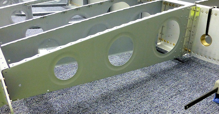
| Step 08: Step 05: Rivet
the modified Inboard Tank Rib to the next inboard angle, this is now
known as Main Rib-L11-IT Builder Note: The top angle is removable for fuel tank install. The large hole is to allow room for the fuel line and fuel gauge connections. Spacer Plates at the front of the fuel tank ribs will be installed on Page 15.05 Step: 05 |
 |
|||||||||||
| Step 09:Rivet a front trimmed Rib to the next inboard angle, this is now known as Main Rib-L12 |
 |
|||||||||||
| Step 10: Rivet the
W-1210-R Main Rib with the attached W-1210-B Rib Doubler to the
remaining attach angle,this is now known as Main Rib-L13 |
 |
|||||||||||
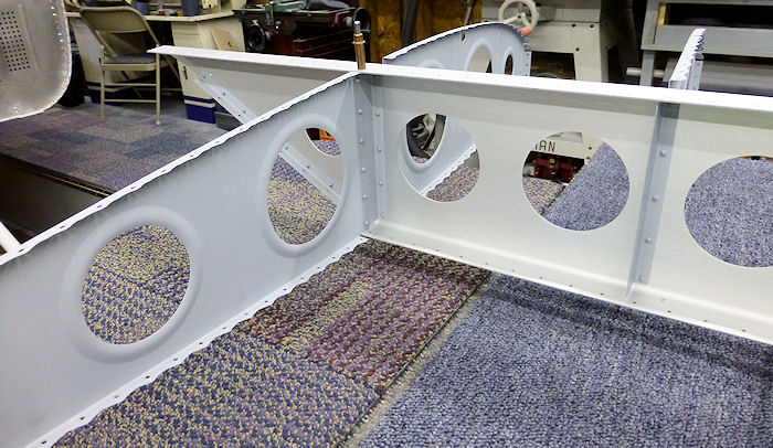
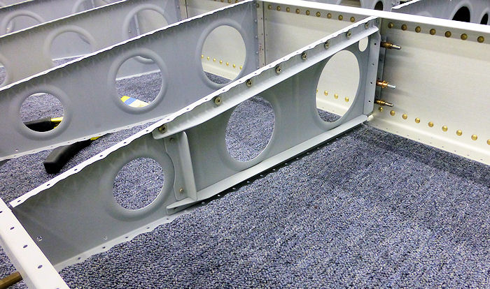
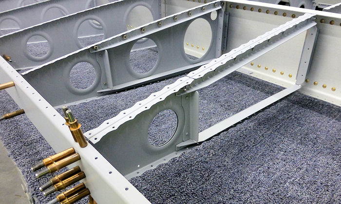
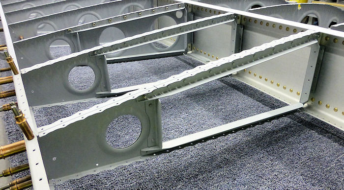
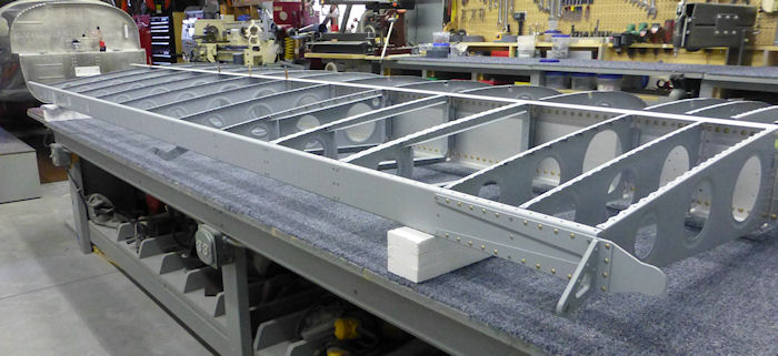
| Step 11: Cleco then
rivet the left Rear Spar Assembly to the aft flanges of the W-1210 Main
Ribs as shown in Figure 4 Builder note: Do not rivet the two W-1216 Hinge Bracket Assemblies at this time Photo 05/30/15 |
 |
|||||||||||
| Builder Note: For items not shown in this section See Alteration 06 | ||||||||||||
| Page 15.04 Wing Ribs |
|
|||||||||||
|
|
||||||||||
|
Disclaimer : Information contained on this Site may be out of date and /or inaccurate - Please Confirm any important data with a reliable source. |