
| Home | Empennage kit | Wing Kit | Fuselage Kit | Finish Kit | Power Plant Kit | Avionics | Paint | Interior | Home |
|
|
|||||||||||
|
|||||||||||
| Home | Alterations | Vendors | Builders Log | Home |
| Alteration 06: Wing Tanks |
|
||||||||||||
| Page 06.01 Fuel Lines | NOTE: Any alteration will require it to be registered as Experimental-Amateur Built E-AB | ||||||||||||
|
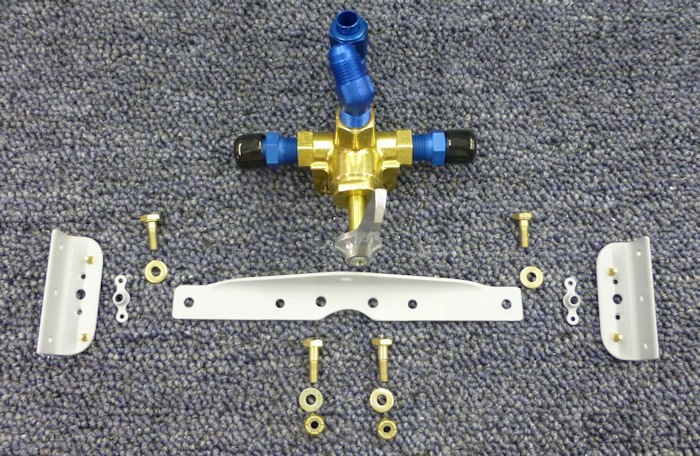
Parts
|
This alteration will install fuel tanks in the wings and modify the fuel system for this alteration
|
||||||||||||
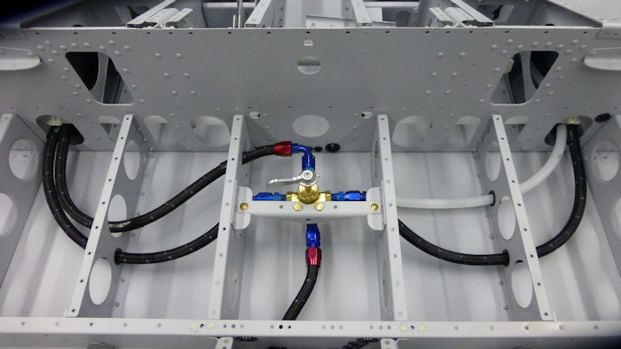
| Step 01: Build parts to
install a four port fuel valve model no. 67474 08/30/12 |
 |
||||||||||||
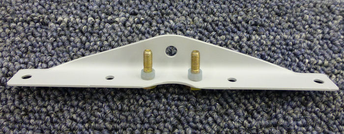
| Step 02: Install two
short pieces of silicone fuel line on bolts. 11/3012 |
 |
||||||||||||
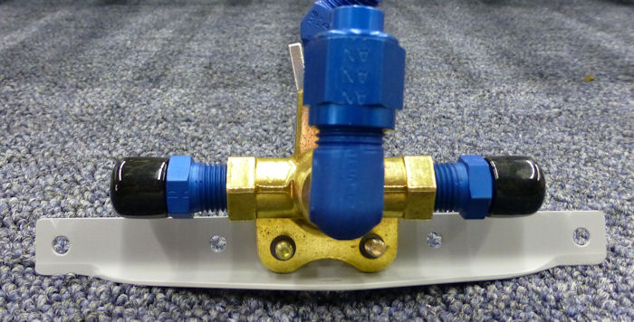
| Step 03: Install the
four port fuel valve to the valve support angle. 08/30/12 |
 |
||||||||||||
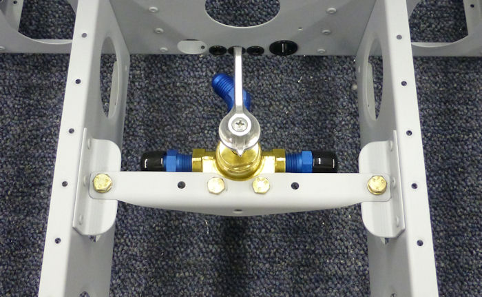
| Step 04: Rivet the
nutplates to the support angles then rivet the angles to the F-1212 L &
R center ribs. Install the valve support angle. 08/30/12 |
 |
||||||||||||
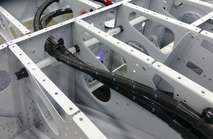
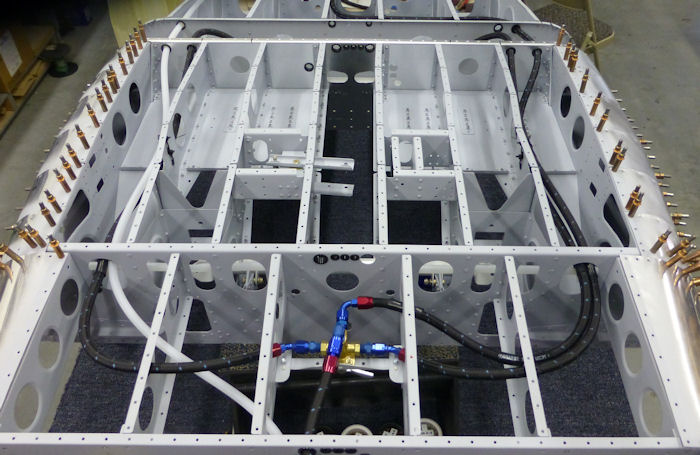
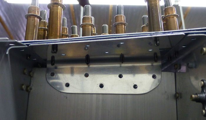
| Step 05: Install fuel
lines as shown in photo Note: Install heat shrink at all possible wear points, only heat enough to stop the tubing from sliding. Note: A fuel pump was added in the line to the back of the fuel valve to pump fuel from the header Tank. 11/12/12 See: 06.02 Fuel Pumps |
 |
||||||||||||
| Step 06: Tie-rap as shown. |
 |
||||||||||||
| Step 07: Add bulk-head
fittings see 06.02.05. Doubl check before install bottom skins. 10/06/12 |
 |
||||||||||||
|
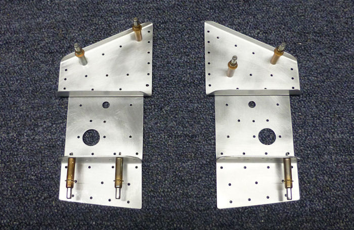
Step 08: Make some new parts out of 2024T3 .040. Photo of parts are after step 11. 03/10/13 |
 |
||||||||||||
| Step 09: Match drill 3 new holes. |
 |
||||||||||||
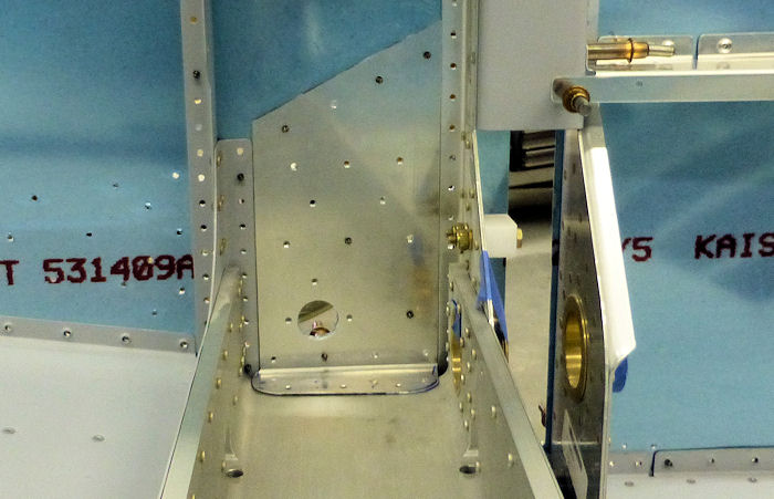
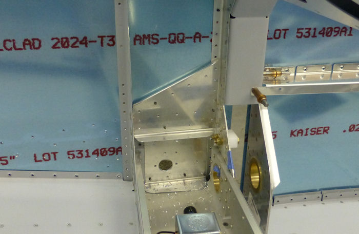
| Step 10: Replace top
clip with a taller one made from .040 2024T3 as shown in photo at right. The hole is for the fuel line from the wing tank. This will also act as the landing gear reinforcement. |
 |
||||||||||||
| Step 11: Make a doubler
as shown and match drill
all holes. This doubler will help transfer the rotational force from the landing gear to skin in front of the spar and the F-1248 armrest , the 90°bends help keep it from buckling. The bottom 90° flange will also be used to hold the fuel pump cover see page: 06.02 step: 04 |
 |
||||||||||||
| Page 06.01 Fuel Lines |
|
|
|
||||||||||
|
Disclaimer : Information contained on this Site may be out of date and /or inaccurate - Please Confirm any important data with a reliable source. |