|
Page 11.06
Emp Attach |
|
Step 01:
Machine countersink 100° the nutplate attach rivet holes called out in
Figure 1.
08/23/10 |
 |
|
Step 02: Rivet the
nutplate onto the inside of the F-1287 Servo Tray using hardware called
out in Figure 1. |
|
|
Step 03: Rivet the F-1287J
Doublers to the F-1287A Servo Tray. Orient and use rivets as called out
in Figure 1. |
|
|
Step 04: Cleco the ES
MSTS-T3-7A-2 Pitch Trim Servo and the F-1278A Servo Tray as shown in
Figure 2. |
|
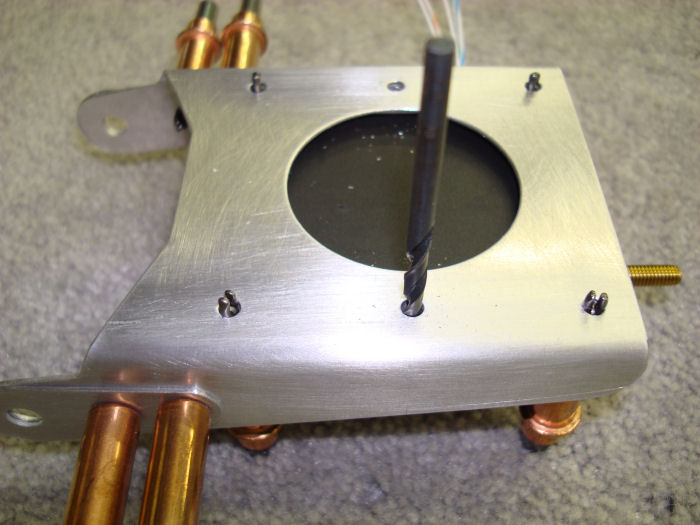
Step 05:
Match-Drill #27 the center holes, and final-drill #27 the end holes in
the F-1287B Doublers into the ES MSTS-T3-7A-2 Pitch Trim Servo and
F-1287A Servo Tray as shown in Figure 2.
08/23/10 |
 |
|
Step 06:
Install the ES MSTS-T3-7A-2 Pitch Trim Servo to the F-1287A Servo Tray
using hardware called out in |
|
|
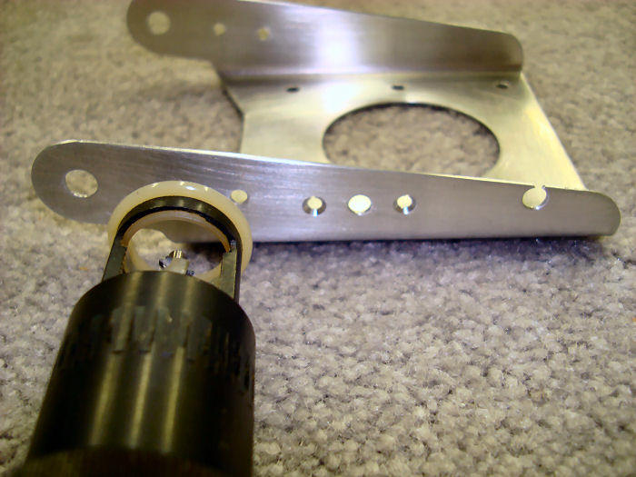
Step 07: Clamp the spade
connectors for Steps 11 and 12 as shown in Figure 3. Strip 1/2" of
insulation from the end of a wire lead. Twist the copper strands
together, and fold the twisted strands in half. Insert the folded wire
into the barrel of the connector to the insertion depth, measure depth
from the edge of the barrel ( as opposed to the edge plastic sheath ).
Crimp the wire, make one crimp to compress the barrel on the bare copper
wire and one crimp to compress the barrel on the wire insulation. |
|
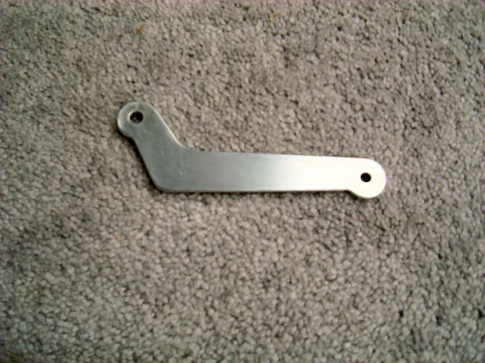
CAUTION: In Step 8 deburr only enough to locate
the bushing.
Step 08:
Deburr the F-1287C Link called out in Figure 4. Deburr the 1287 Servo
Tray called out in Figure 6.
08/23/10 |
 |
|
Step 09:
Insert the polymer bushing into the F-1287C Link as shown in Figure 4.
Insert the polymer bushing into the F-1287A Servo Tray as shown in
figure 6. |
|
|
Step 10:
File the polymer bushings inserted in the previous step. The bushings
must be greater than the thickness of the
part and less than the dimension given in
Figure 5. |
|
|
Step 11:
String the ES MSTS-T3-7A-2 Pitch Trim Servo wire through the called out
snap bushing and insert the snap bushing into the F-1287A Servo Tray as
shown in figure 6. |
|
|
Step 12:
Crimp a male spade connector to one of the white wires of the ES
MSTS-T3-7A-2 Pitch Trim Servo wire. Crimp female spade connectors to
each remaining trim wires as shown in Figure 6. |
|
|
Step 13:
Crimp one one ES 421-0108 Female spade connector to one of the white
wires of the WH-P30 Trim wires that exits the aft end of the
Tailcone assembly. Crimp ES 421-0107 male spade connectors to each of
the remaining trim wires. For trim wires reference see Page 10-08. |
|
|
Step 14:
String the ES MSTS-T3-7A-2 Pitch Trim Servo wire into the cushioned
clamp. then temporarily install the cushioned clamp to the F-1287A Servo
Tray as shown in Figure 6. |
|
|
Page 11.06
Emp Attach |
|
