
| Home | Empennage kit | Wing Kit | Fuselage Kit | Finish Kit | Power Plant Kit | Avionics | Paint | Interior | Home |
|
|
|||||||||||
|
|||||||||||
| VERTICAL STAB | RUDDER | ANTI-SERVO TAB | STABILATOR | TAILCONE | EMP ATTACH | EMP FAIRINGS | BUILDERS LOG |
| Page 10.02 Tailcone |
|
|||||||||||||||
|
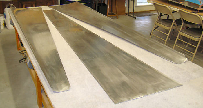
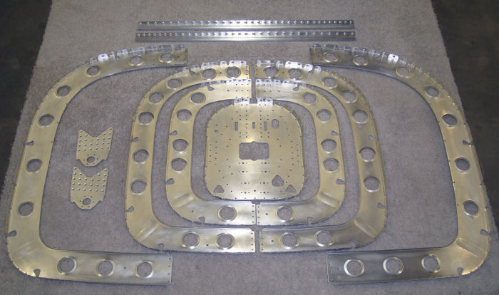
Step 01-A:
Identify the Tailcone Skins. The F-1278 Top Skin does not have a J-stiffener formed on either of the long edges. The Upper Left and Right Side tailcone skins have a J-stiffener formed on one edge. The left skin is mirrored by the right. 08/17/10
|
 |
|||||||||||||||
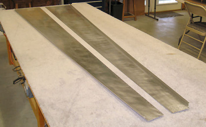
Step 01-B: The Left & Right Side Skins have a
J-stiffener formed on only one edge.
|
 |
|||||||||||||||
|
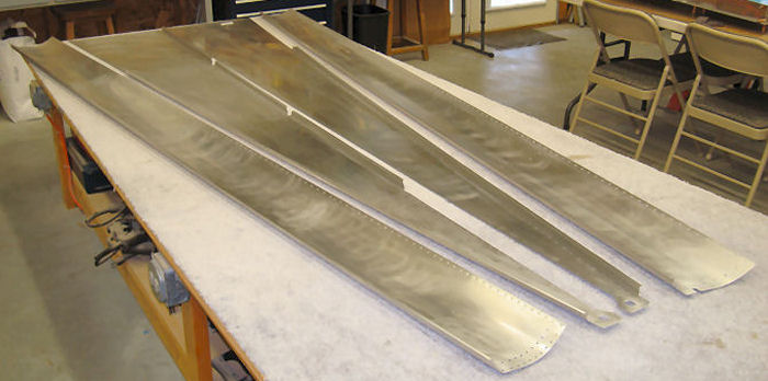
Step 01-C:
The F-1281-L & R Lower side skins have a
J-stiffener formed on only one edge. The F-1282-L Bottom Left Skin has J-stiffeners form on both of long edges. The F-1282-R Bottom Right Skin has a J-stiffener formed on only one edge.
Builder Note: This step completed after Step:10-06-01 |
 |
|||||||||||||||
|
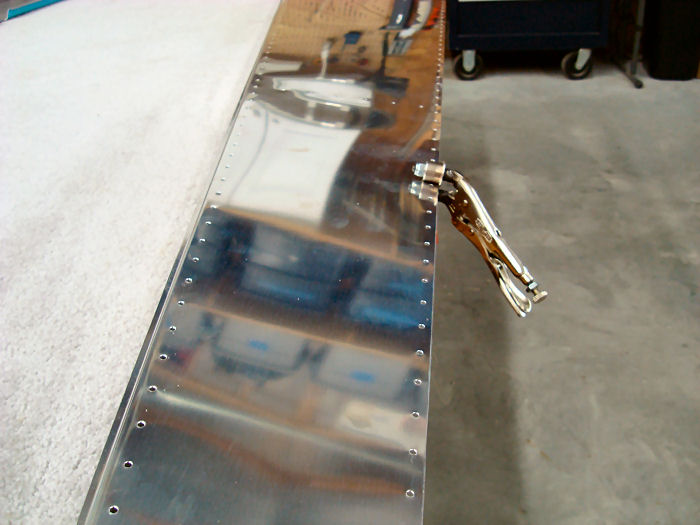
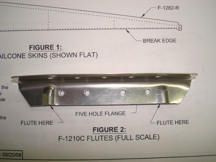
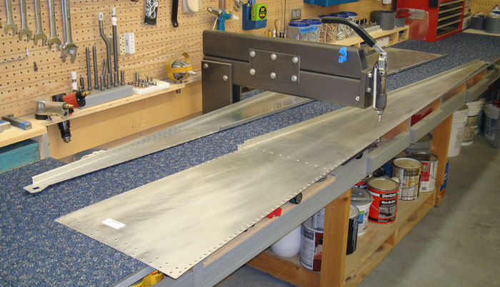
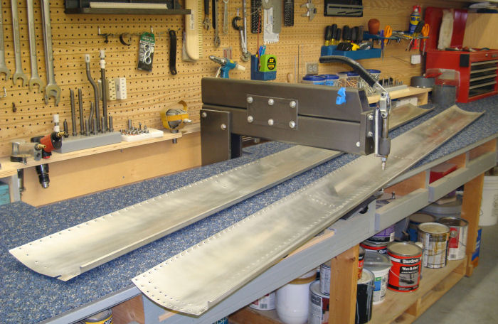
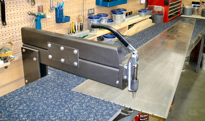
Step 02: Prepare the skins
shown in Figure 1 for a lap joint by de-burring and breaking ( Section
5K ) the edges. The edges to be lap joints are called out in Figure 1.
Both edges of the F-1278 Top skin must break in the same direction. The
remaining skins must break in the same direction as the J-Stiffener.
Begin with the F-1282-R Bottom Right skin, since it is least likely to
be seen. when breaking the edges of the F-1278 Top Skin gradually
increase the break angle toward the aft end. 08/17/10 Builder Note: This step completed after Step: 10-06-01 See 10-06-01 |
 |
|||||||||||||||
|
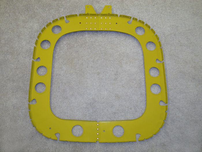
Step 03: Flute the F-1210C
Angle at the places called out in Figure 2. Each flute needs to 'hump'
in the same direction as the five- hole flange. With the five hole
flange pointing up, align the holes in the four-hole flange of the angle
to the full scale illustration in Figure 2, Increase the two flutes
until the five-hole flange matches the curve shown in Figure 2. 08/11/10 |
 |
|||||||||||||||
|
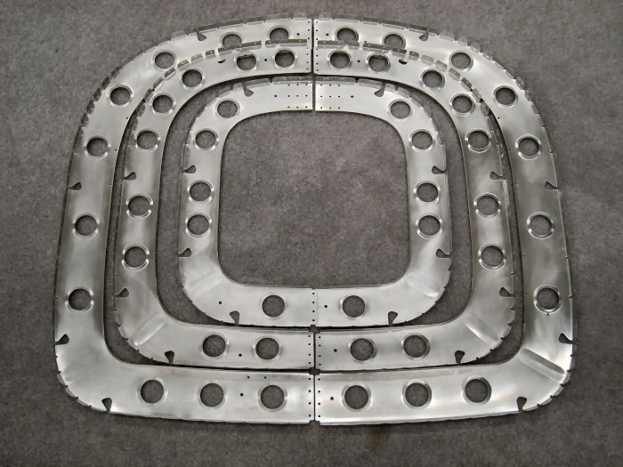
Step 04: Flute the
F-1208-L & R, F-1209-L & R and F-1210A-L & R Fuselage Frames to align
the flange holes. Flute the 'hump' of any humped flanges toward the web
of each fuselage frame. NOTE: The F-1208A Were Plate May be rotated 180º once prior to replacement. 08/11/10 Builder Note: Hold |
 |
|||||||||||||||
|
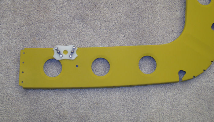
Step 05:
Rivet The F-1208A Wear Plate to the F-1208-R Fuselage Frame as shown in
Figure 3. Builder Note: Were plate on hold. If this Plate is to be removed after wear the fasteners may be hard to drill out. ALTERATION Add nutplates to the back of the Wear Plate. 01/14/11 |
 |
|||||||||||||||
|
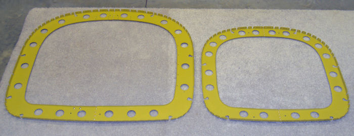
Step 06:
Cleco, then rivet the F-1208-L to the F-1208-R. Cleco then rivet the
F-1209-L to F-1209-R as shown, using rivets called out in Figure 3. Hereafter, refer to the riveted F-1208-L & R as the F-1208 Frame and the F-1209-L & R as the F-1209 Frame. ALTERATION Rivets Used |
 |
|||||||||||||||
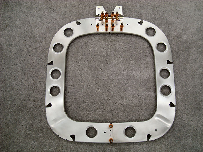
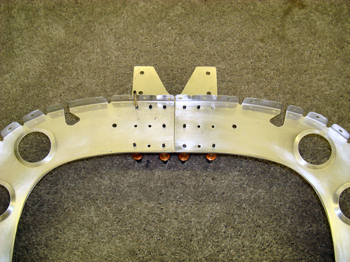
| Step 07: Cleco the F-1210B Plate and F-1210C Angle to the
F-1210A-L & R Fuselage Frames as shown in Figure 4. 08/11/10 |
 |
|||||||||||||||
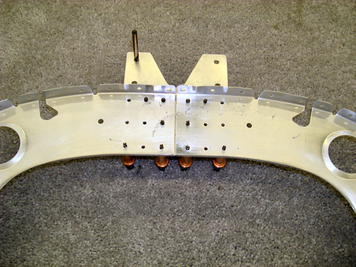
| Step 08: Match-Drill #30 the two holes from the F-1210A-L & R
Fuselage Frames into the F-1210C Angle as called out in Figure 4. Disassemble and deburr. 08/11/10 |
 |
|||||||||||||||
| Step 09: Final-Drill #12 the F-1210B Plate at the holes called
out in Figure 4. 08/11/10 |
 |
|||||||||||||||
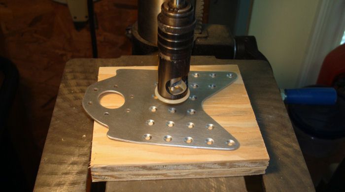
|
Step 09
A:
ALTERATION Machine with a 120° Countersink the F-1211C-L&R Hinge Brackets Photo Note: Some of the Photos on this site will show the Alteration. 01/04/11 .2Hrs |
 |
|||||||||||||||
|
Step 09
B:
ALTERATION Dimple with a 120° Dimple Die The Flanges of the F-128-A&B J-Stiffeners, the F-1028, 1029 &1210 Fuselage Frames, the F-1211A Aft Bulkhead. Do not dimple die the holes associated with the F-1211C-L&R Hinge Brackets and the top four center holes in the F-1211A Aft Bulkdead 01/04/11 1.0 Hrs |
 |
|||||||||||||||
|
Step 09
C:
ALTERATION Dimple with a 120° Dimple Die the holes in the F-1282-R&L Bottom Skins 01/04/11 .7 Hrs |
 |
|||||||||||||||
|
Step 09
D:
ALTERATION Dimple with a 120° Dimple Die the F1281-L&R Lower Side Skins the F1280-L&R Side Skins Do not dimple die the Static Port holes the F1278-L&R Upper Side Skins 01/04/11 2.2 Hrs |
 |
|||||||||||||||
|
Step 09
E:
ALTERATION Dimple with a 120° Dimple Die the F-1278 Top Skin Do not dimple die the holes associated with F-12106 Fwd Skin Rib, the F-1210C Angle and the four top center holes of the F-1211A Bulkhead 01/04/11 .4 Hrs |
 |
|||||||||||||||
| Step 10: Rivet the F1210A-L to the F-1210A-R Fuselage Frame, The
F1210B Plate and the F-1210C Angle together using rivets called out in
Figure 4. Hereafter, refer to the riveted F-1210A-L & R, F-1210B and F-1210C as the F-1210 Frame ALTERATION Rivets Used |
 |
|||||||||||||||
| Page 10.02 Tailcone |
|
|||||||||||||||
| VERTICAL STAB | RUDDER | ANTI-SERVO TAB | STABILATOR | TAILCONE | EMP ATTACH | EMP FAIRINGS | BUILDERS LOG |
|
||||||||||
|
Disclaimer : Information contained on this Site may be out of date and /or inaccurate - Please Confirm any important data with a reliable source. |