
| Home | Empennage kit | Wing Kit | Fuselage Kit | Finish Kit | Power Plant Kit | Avionics | Paint | Interior | Home |
|
|
|||||||||||
|
|||||||||||
| VERTICAL STAB | RUDDER | ANTI-SERVO TAB | STABILATOR | TAILCONE | EMP ATTACH | EMP FAIRINGS | BUILDERS LOG |
| Page 10.09 Tailcone |
|
|||||||||||
|
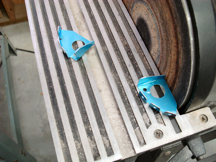
Step 01:
Remove the area shown hatched to Separate the F-1238-L & R Snap Bushing
Brackets as shown in Figure 1. 08/23/10 |
 |
|||||||||||
|
Note: Steps 2 through 6 explain
installation for the F-1279-L Upper Left Skin and F-1238-L Snap Bushing
Bracket. Installation for the F-1279-R Upper Right Skin and F-1238-R
Snap Bushing Bracket is a mirror of the left and should be done at the
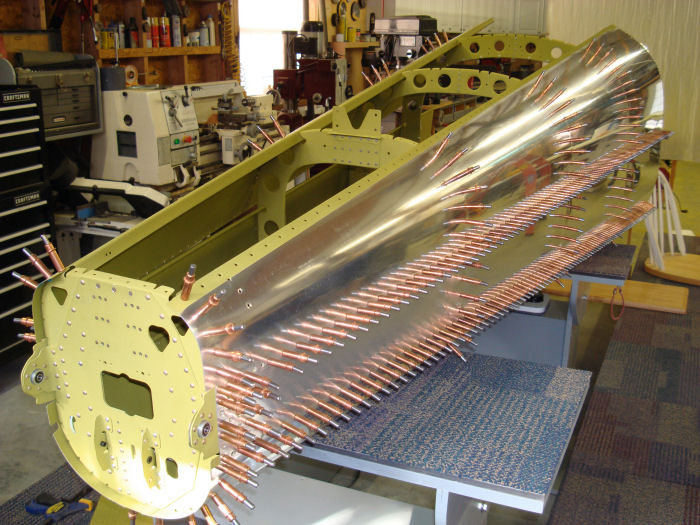
same time. Step 02: Hook the F-1279-L Upper Left Skin J-Stiffener into the cut outs in the F-1208, F-1209 and F1210 Frames. Cleco the upper left skin to the frames and F-12080-L Left Side Skin as shown in Figure 2. 01/25/11 |
 |
|||||||||||
|
Step 03: Cleco the
F-1238-L Snap Bushing Bracket to the F-1279-L Upper Left Skin as shown
in Figure 2. Step 04: With a 12" extended bit, Match-Drill #30 the holes called out in the F-1279-L Upper Left Skin J-stiffener into the F-1238-L Snap Bushing Bracket. Cleco the first hole before drilling the next Then remove, deburr and re-cleco. 01/25/11 |
 |
|||||||||||
|
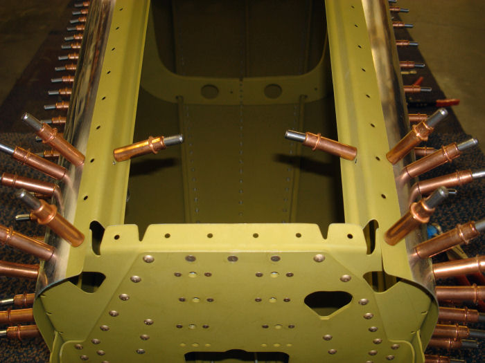
Step 05:
Rivet the F-1238-L Snap Bushing Bracket to the F-1279-L Upper Left Skin
Using rivets called our in Figure 2. Step 06: Insert the snap bushing into the F-1238L Snap Bushing Bracket called out in figure 2. 01/25/11 Builder Note: Still Waiting for 2" Yoke to install the last 6 Rivets from page 10.04 |
 |
|||||||||||
| Step 07: Route a string from the forward end of the existing structure to the F-1211 Assembly. The string will go through the F-1238-L Snap Bushing Bracket, out through the left rudder control cable cutout. then back in through the right control cable cutout and through the F-1238-R Snap Bushing Bracket as shown in Figure 2. Return the end of the string to the forward end of the existing structure. Tape both ends of the string to the inside surface of the bottom skin. |
Builder Note: This step will be preformed using my fiberglass pull rods at the time necessary. |
|||||||||||
| Step 08: Place masking tape over all the holes that are within
seven inches of the forward edge of each tailcone skin. The masked holes
will be left open for the remainder of this section. |
Builders
Note: Leave clecos in all the holes that are within seven inches of the
forward edge of each tailcone skin. This will help keep the alignment of
the skins. Clecos moved to the inside after tailcone finished. |
|||||||||||
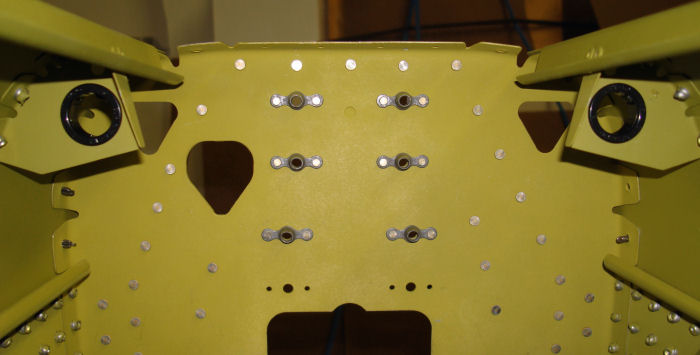
| Step 09: Rivet all of the open holes of the F-1280-L & R Left and
Right Side Skins. Rivet only the holes in the F-1279-L & R Upper Left
and Right Side Skins that are common to the left or right side skins.
Capture the F-1211C Hinge Bracket when riveting the aft end of each left
and right side skin. 01/25/11 |
Missing Photo | |||||||||||
| Page 10.09 Tailcone |
|
|
|
||||||||||
|
Disclaimer : Information contained on this Site may be out of date and /or inaccurate - Please Confirm any important data with a reliable source. |