| Home | Empennage kit | Wing Kit | Fuselage Kit | Finish Kit | Power Plant Kit | Avionics | Paint | Interior | Home |
 |
|||||||||||
|
|||||||||||
| VERTICAL STAB | RUDDER | ANTI-SERVO TAB | STABILATOR | TAILCONE | EMP ATTACH | EMP FAIRINGS | BUILDERS LOG |
| Page 10.08 Tailcone |
|
|||||||||||
| Step 01: Turn the assembly over so the frames are pointing up. Support the assembly with two sawhorses, one at the F-1208 Frame and one at the F-1210 Frame. | Builder note: Step: 10-06-07, 10-06-08, 10-06-09 and 10-07-01 will be accomplished using my work table and bungee cords from the overhead paint rack. Step: 10-07-02 and 10-07-03 will be accomplished using my assembly area work stands. |
|||||||||||
|
Step 02: Cleco the F-1211
Assembly to the aft end of the existing structure as shown in Figure 1. 01/21/11 Builder Note: Still Waiting for 2" Yoke to install the last 6 Rivets from page 10.04 |
 |
|||||||||||
|
Step 03: Hook the
J-Stiffener of the F-1280-L & R Left and Right Side Skins into the
notches of the F-1208, F-1209 and F-1210 Frames. Cleco
the left and right side skins to the existing structure as shown in
Figure 1. 01/25/11 Builders Note: Assembly area work stands adjust to the profile of the load applied. |
 |
|||||||||||
|
Step 04: Route a string
from the forward end of the existing structure, through the center of
each frame, to the F-1211 Assembly. The string will go out through one
of the stabilator control cable cutouts and back in through the other
stabilator control cable cutout as shown in figure 1. Return the end of
the string to the forward end of the existing structure. Tape both ends
of the string to the inside surface of the bottom skin. Note: For the remaining steps on this page, leave the plastic tie wraps loose on the F-1208 Frame and the J-Stiffener forward of the F-1208 Frame for additions later. |
Builder Note: This step will be preformed using my fiberglass pull rods at the time necessary. |
|||||||||||
|
Step 05:
Rout the WH-P30 Trim Wires. Start six inches aft of the F-1211 Assembly,
route the trim wires through the snap bushing. Route the trim wires
inside the J-stiffener 'hook' of the F-1281-L Lower Left Skin to the
forward edge of the existing structure. At the holes provided in the
J-stiffener aft of the F-1208 Fuse Frame Secure the trim wires using
plastic tie wraps. Coil the remainder of the trim wires and secure the
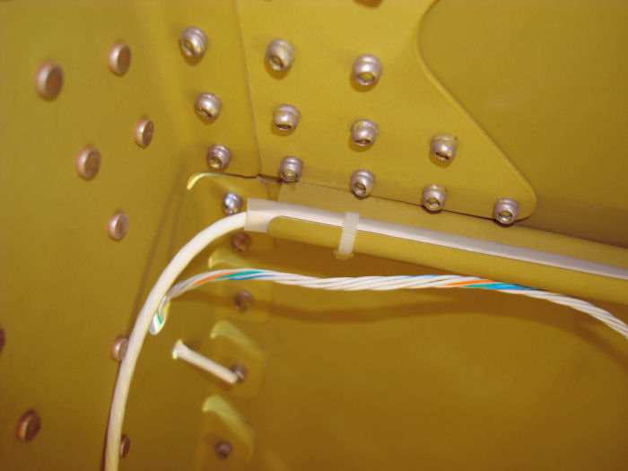
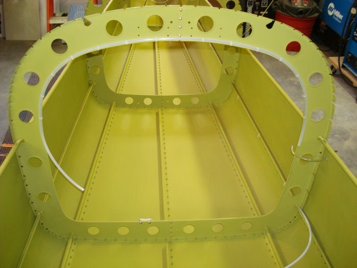
coil to the inside of the lower left skin with tape. Builder Note: Snap bushing will be installed after Painting. Used 1/4" OD Polypropylene tubing for raceway, this will allow easy replacement if necessary. Extra tie wrap installed. 01/25/11 |
 |
|||||||||||
| Step 06: Follow the 'Installing the Static Air System' Instructions to Install the Left and right side static sources into the F-1280-L & R Left and Right Side Skins in the locations called out in Figure 2. |
On hold for new parts The new system photo will be shown in Alterations |
|||||||||||
|
Step 07:
Install the end of the 1/8"ID Clear Plastic Tube over the right static
source. Route the 1/8"ID Tube along the inside flange of the F-1208
Frame. Follow the inside flange of the F-1208 Frame to the left side.
Secure the tube with plastic tie wraps through the holes along the
flange. install the loose end of the 1/8" ID Clear Plastic Tube to the
plastic tee. Position the plastic tee at the same height as the
J-stiffener located directly above the static source. Install the end of
a separate piece of 1/8" ID Clear Plastic Tube to the left static source
and the and the other end of that tube to the plastic tee. Builder Note: Alteration 03 1/4" OD Polypropylene tube will be used for the entire system 01/25/11 I will Order new parts. |
 |
|||||||||||
| Step 08: Install a 1/4" long piece of 1/8" ID clear Plastic Tube to the remaining leg of the plastic tee. Connect one end of the PT 1/4" OD Polypropylene tube to that same leg of the plastic tee. Route the polypropylene tube down the inboard flange of the frame, then to the J-stiffener of the F-1281-l Lower left side skin as shown in Figure 2. Route the tube inside the J-stiffener 'hook" of the lower side skin with the WH-P30 shown in Detail A-A, to the forward edge of the existing structure . Coil the remainder of the tube and secure the coil to the inside of the lower left side skin with tape or string. | On hold for new parts The new system photo will be shown in Alterations |
|||||||||||
| Page 10.08 Tailcone |
|
|
|
||||||||||
|
Disclaimer : Information contained on this Site may be out of date and /or inaccurate - Please Confirm any important data with a reliable source. |