
| Home | Empennage kit | Wing Kit | Fuselage Kit | Finish Kit | Power Plant Kit | Avionics | Paint | Interior | Home |
|
|
|||||||||||
|
|||||||||||
| VERTICAL STAB | RUDDER | ANTI-SERVO TAB | STABILATOR | TAILCONE | EMP ATTACH | EMP FAIRINGS | BUILDERS LOG |
| Page 09.03 Stabilator |
|
|||||||||||
|
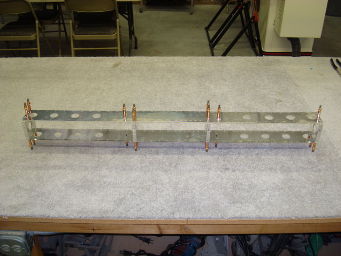
NOTE: The proper orientation of the spars
( top, bottom, forward, aft ) is critical throughout the Stabilator
assembly. Make sure all flange holes align with spar cap holes. Step 01: Cleco the HS-1209 Spar Caps Spacers, the HS-1212 Inspar Ribs and the two HS-1211 Spar Caps together as shown in Figure 1. Orient the spar caps so that the closely spaced holes in the top spar cap align with the closely spaced holes in the bottom spar cap, and machine countersink holes ?? face away from the inspar ribs. Orient the inspar ribs with the tooling holes positioned as shown in Figure 1. When all are oriented correctly, the lightening hole in web of each inspar rib will align when sighting through all of the inspar ribs from the end. 08/06/10 |
 |
|||||||||||
|
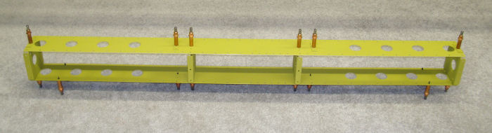
Step 02: Rivet the HS-1211
Spar Caps, HS-1211 inspar Ribs, and HS-1209 Spar Cap Spacers together
using rivets called out in Figure 1. Remove any remaining clecos. 11/01/10 |
 |
|||||||||||
|
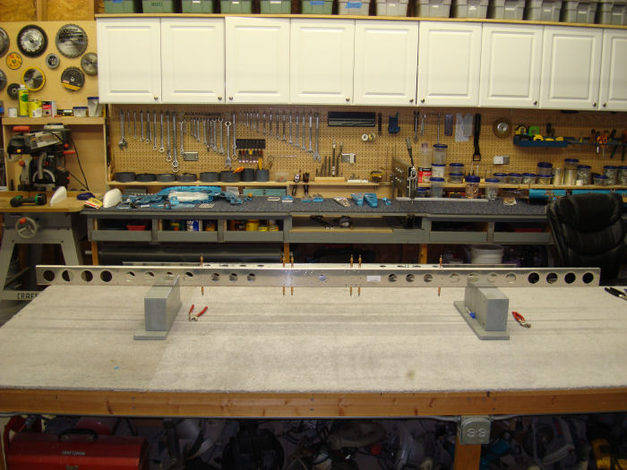
Step 03: Cleco the HS-1202
Fwd and HS- 12003 Aft Spar to the HS-1212 Inspar Ribs, as shown in
Figure 2. Hereafter refer to this subassembly as the Spar Box Assembly.
08/06/10 |
 |
|||||||||||
|
Step 04: Cleco the WD-1207
Upper and WD-1208 Lower Horns to the HS-1202 Fwd and HS-1203 Aft Spars.
Identify the upper horn by the 3/16" identifier hole. Point both of the
horns forward as shown in Figure 2. Mark the top and bottom of the Spar
Box Assembly for reference later. 08/06/10 |
 |
|||||||||||
|
Step 05:
Final-Drill #12 the fastener holes of the WD-1207 Upper and WD-1208
Lower Horns into the webs of both spars as called out in Figure 2.
Insert an AN3 bolt into each hole before drilling the next. Remove the upper and lower horn, deburr the holes and set the horns aside. 08/06/10 |
 |
|||||||||||
|
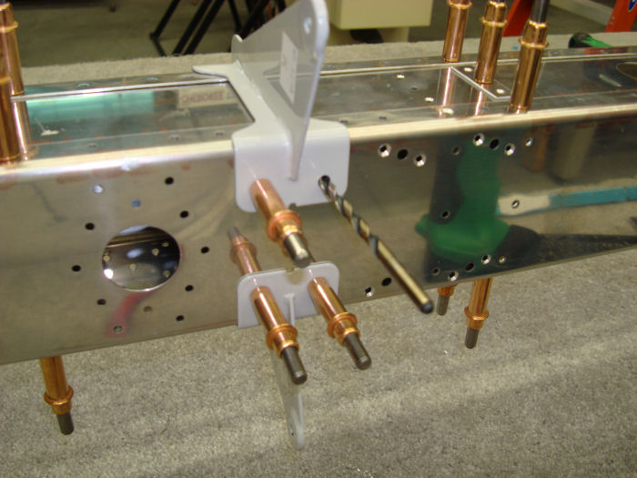
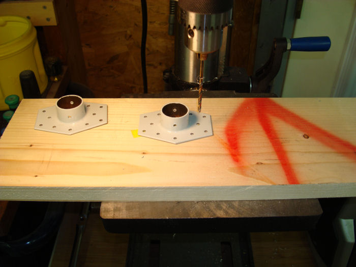
Step 06:
Final-Drill #30 all of the holes in the plate of both of the WD-1222
Counterbalance Brackets. 08/06/10 |
 |
|||||||||||
|
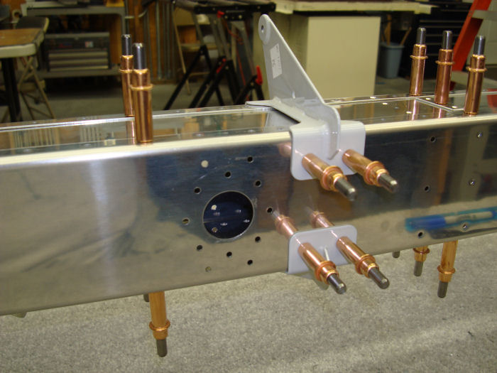
Step 07:
Align each WD-1222 Counterbalance Brackets to the corresponding holes in
the HS-1202 Fwd and HS-1203 Aft Spar. Turn both brackets 90°
and cleco them in position, as shown in Figure 3, Detail A-A. 08/06/10 |
 |
|||||||||||
|
Step 08:
Insert the WD-1223 Counterbalance arm into the forward WD-1222
Counterbalance Bracket ( clecoed to the HS-1202 Fwd Spar ) through the
Spar Box Assembly, then into the aft WD-122 Counterbalance Bracket.
Bring the aft end of the counterbalance arm flush with the aft edge of
the aft counterbalance bracket, and orient the counterbalance arm as
shown in Figure 3. Clamp the counterbalance arm to the counterbalance
brackets. 08/06/10 |
 |
|||||||||||
|
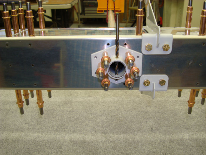
Step 09:
Match-Drill #30 the two holes from the neck of each WD-1222
Counterbalance Bracket into the WD-1223 Counterbalance Arm. Cleco as you
go. Then final-drill #12 per call-out in figure 3, Detail B-B.
Temporarily insert an AN3-14A bolt after final-drilling the first
hole.
08/06/10 |
 |
|||||||||||
|
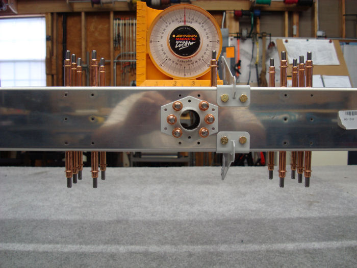
Step 10:
Rotate the counterbalance arm and counterbalance brackets 90°, make sure
the top edge of the counterbalance arm ( see call-out in Figure 3,
Detail B-B ) is oriented with the top side of the Spar Box Assembly.
Mark the counterbalance brackets in relation to the Spar Box Assembly ,
and counterbalance arm. Remove the counterbalance arm and brackets, remove the HS-1202 Fwd and HS-1203 Aft Spar. Deburr holes, and clear away any chips. |
||||||||||||
| Page 09.03 Stabilator |
|
| VERTICAL STAB | RUDDER | ANTI-SERVO TAB | STABILATOR | TAILCONE | EMP ATTACH | EMP FAIRINGS | BUILDERS LOG |
|
||||||||||
|
Disclaimer : Information contained on this Site may be out of date and /or inaccurate - Please Confirm any important data with a reliable source. |