
| Home | Empennage kit | Wing Kit | Fuselage Kit | Finish Kit | Power Plant Kit | Avionics | Paint | Interior | Home |
|
|
|||||||||||
|
|||||||||||
| VERTICAL STAB | RUDDER | ANTI-SERVO TAB | STABILATOR | TAILCONE | EMP ATTACH | EMP FAIRINGS | BUILDERS LOG |
| Page 09.06 Stabilator |
|
|||||||||||
|
Step 01:
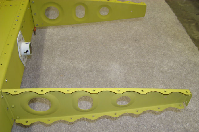
Rivet the HS-1214 Rib Clips to the HS-1203 Aft Spar per call-outs in
Figure 1. Note the orientation of each rib clip, and be sure that all
three holes of each rib clip align to all three holes of the aft spar
before riveting. 11/01/10 Builder Note: Photo out of sequence |
 |
|||||||||||
|
Step 02: Radius the edges
at the narrow end of the HS-1204 Fwd In-bd Ribs and HS-1205 Fwd Out-bd
Ribs as shown in Figure 2. A great way to form the radius is with a fine file. Deburr all of the ribs. Builder Note: Deburr, Straighten and mark all ribs. Hold for priming 08/10/10 |
 |
|||||||||||
|
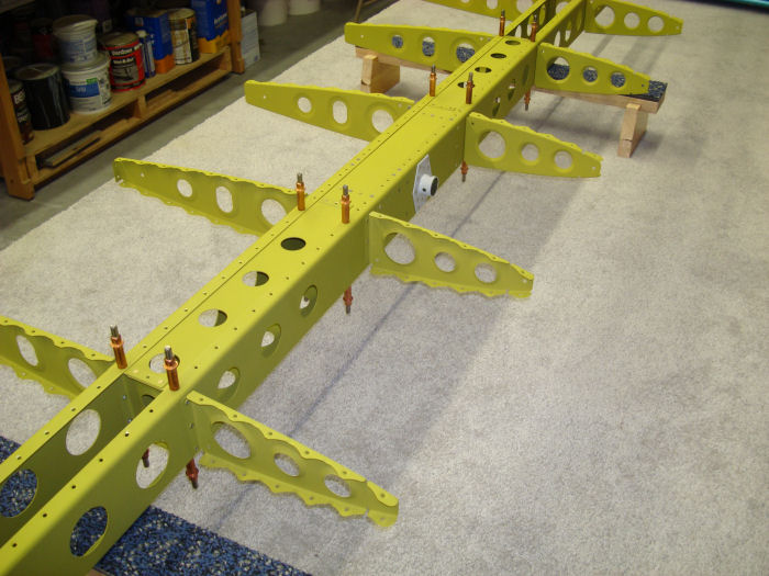
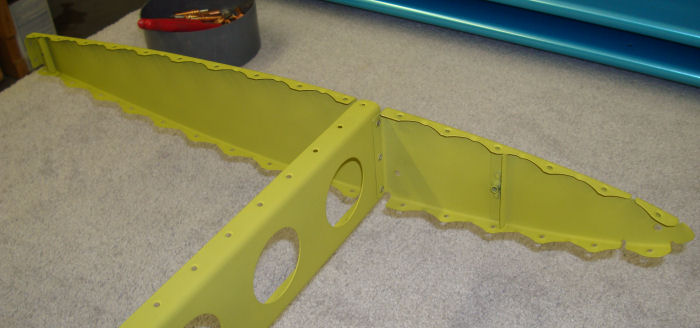
NOTE: Figure 3 illustrates the installation of the ribs for the right
side of the stabilator. Steps 3, 4, and 5 describe installation for the
ribs on the right side of the Stabilator. Installation for the ribs on
the left side of the Stabilator is a mirror of the right. Perform the
remaining steps on this page on both sides of the stabilator. Flute ribs
as necessary per Section 5N. Step 03: Rivet the HS-1216 Aft Main Ribs and the 1206 in-bd Main Rib to the HS-1214 Rib Clips per call-out in Figure 3. Step 04: Rivet the HS-1204 Fwd In-bd Ribs to the DS-1202 Fwd Spar per call-out. Include the forward flange of the HS-1206 In-bd Main Rib when installing the outer most fwd in-bd rib. Orient all the rib flanges as shown in Figure 3. 11/01/10 |
 |
|||||||||||
|
Alteration 02 Rivet four nutplates and reinforcement angles to the 2 HS-1205 and the HS1207 Ribs |
 |
|||||||||||
|
Step 05:
Rivet the HS-1205 Fwd Out-bd Rib to the HS-1207 Out-bd Main Rib through
the HS_1202 Fwd Spar. Orient the flanges of the fwd out-bd rib and the
out-bd main rib so that they point inboard as shown in Figure 3. 11/01/10 Hereafter refer to the Spar box Assembly with all of the ribs attached as the Stabilator Skeleton Assembly. |
 |
|||||||||||
| Page 09.06 Stabilator |
|
| VERTICAL STAB | RUDDER | ANTI-SERVO TAB | STABILATOR | TAILCONE | EMP ATTACH | EMP FAIRINGS | BUILDERS LOG |
|
||||||||||
|
Disclaimer : Information contained on this Site may be out of date and /or inaccurate - Please Confirm any important data with a reliable source. |