
| Home | Empennage kit | Wing Kit | Fuselage Kit | Finish Kit | Power Plant Kit | Avionics | Paint | Interior | Home |
 |
|||||||||||
|
|||||||||||
| VERTICAL STAB | RUDDER | ANTI-SERVO TAB | STABILATOR | TAILCONE | EMP ATTACH | EMP FAIRINGS | BUILDERS LOG |
| Page 09.05 Stabilator |
|
|||||||||||
|
Step 01:
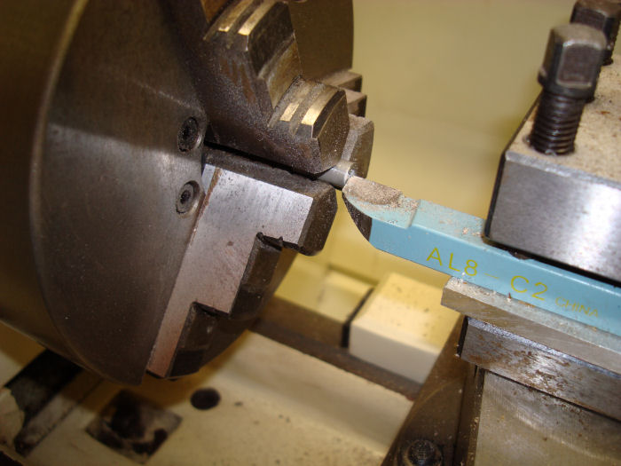
Cut the 5/16" aluminum tube to make four HS-1210 Hinge Stops per
dimensions in Figure 1. Builder Note: cut with band saw and ends squared off with Lathe. Final length .667" 21/32" = .656" 11/16" = .687" 08/06/10 Note: Re-cut to .662 11/12/10 |
 |
|||||||||||
|
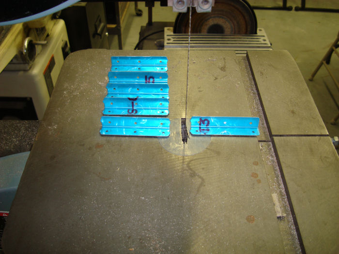
Step 02: Separate The
HS-1214 Rib Clips by removing the material hatched in Figure 2. 08/06/10 |
 |
|||||||||||
|
Step 03:
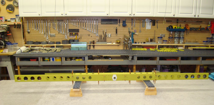
Cleco the Spar Box Assembly back together. Check alignment of HS-1202
Fwd and HS-1203 Aft Spar flanges holes to the corresponding holes in
both HS-1211 Spar Caps. All spar flanges holes must align with spar cap
holes. 11/01/10 |
 |
|||||||||||
|
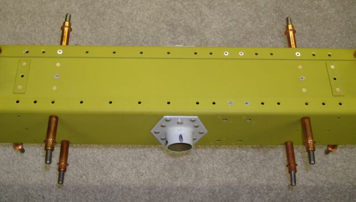
Step 04: Rivet the
previously countersunk holes in both flanges of the HS-1202 Fwd and
HS-1203 Aft Spar to the HS-1211 spar Caps per call-out in Figure
3. 11/01/10 |
 |
|||||||||||
|
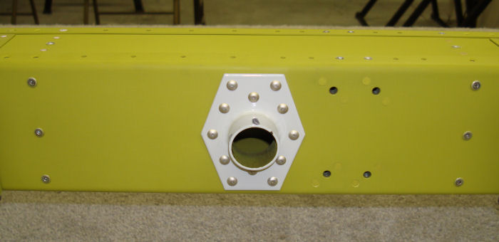
Step 05:
Rivet the HS-1202 Fwd and HS-1203 Aft Spar to the Inboard HS-1212 Inspar
Ribs using rivets called out in Figure 3. 11/01/10 |
 |
|||||||||||
| Page 09.05 Stabilator |
|
| VERTICAL STAB | RUDDER | ANTI-SERVO TAB | STABILATOR | TAILCONE | EMP ATTACH | EMP FAIRINGS | BUILDERS LOG |
|
||||||||||
|
Disclaimer : Information contained on this Site may be out of date and /or inaccurate - Please Confirm any important data with a reliable source. |