
| Home | Empennage kit | Wing Kit | Fuselage Kit | Finish Kit | Power Plant Kit | Avionics | Paint | Interior | Home |
|
|
|||||||||||
|
|||||||||||
| VERTICAL STAB | RUDDER | ANTI-SERVO TAB | STABILATOR | TAILCONE | EMP ATTACH | EMP FAIRINGS | BUILDERS LOG |
| Page 09.07 Stabilator |
|
|||||||||||
|
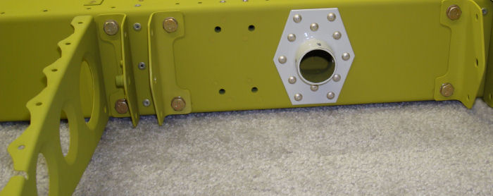
Step 01:
Install the HS-1213A In-bd and HS-1213B Out-bd Hinge Brackets to the
HS-1202 Fwd Spar using the hardware called out in Figure 1. NOTE: Rib Hard side In to support the skin. 11/12/10 |
 |
|||||||||||
|
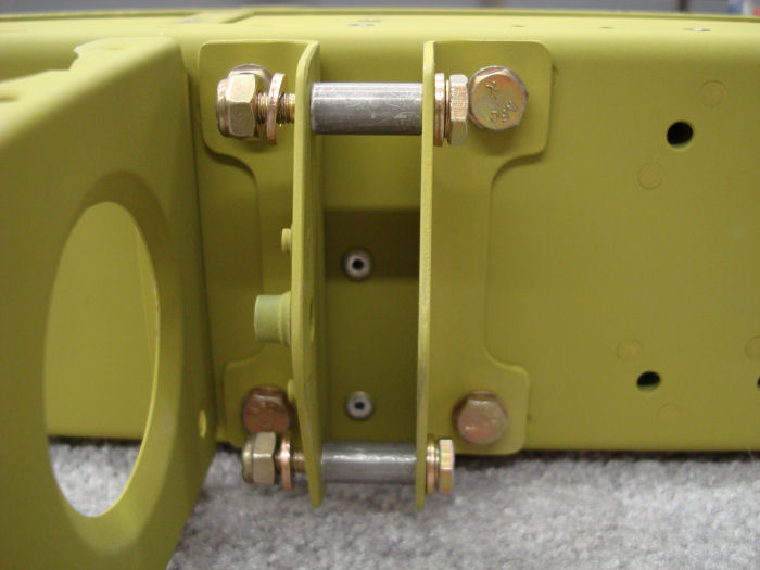
Step 02: Install the
HS-1210 Bushings between the HS-1213A In-bd and HS-1213B Out-bd hinge
Brackets using the hardware called out in Figure 1. When installing each
bushing or tightening the bolt the In-bd and out-bd hinge brackets
should not yield to the bushings. Trim or replace bushings as necessary
to maintain the spacing and angle of the in-bd and out-bd hinge
brackets. NOTE: Ribs attached to the Spar box Assembly not shown in Figure 1. Builder Note: Re-cut to .662 11/12/10 |
 |
|||||||||||
|
NOTE: The HS-1218A Aft Hinge halves were cut to length on Page 8-3, Step
4. Step 03: Mark one of the HS-1218A Aft Hinge halves as right and the other as left, and label the inboard end of each of each hinge as indicated in Figure 2. Step 04: Apply masking tape to the HS-1218-R and HS1218-L Aft Hinges as Shown in Figure 2. Count from the same end of both hinge halves. Mask the HS-1218A-L at the 14th eyelet and the 28th eyelet. Mask the HS-1218-R at the 6th and the 20th. These areas will be omitted when drilling in Step 5. |
 |
|||||||||||
|
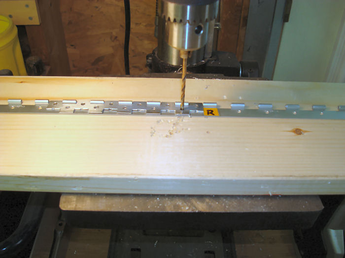
CAUTION: Before performing Step 5 study
the HS-1223 Drill Guide to identify the difference between the notched
edges ( used in Section 8 ) and the un-notched edges used in this
section. NOTE: For tips using the DS-1223 Drill Guide refer to page 8-3, Figure 5, 6, and 7. |
Step 05:
Match-Drill #30 the HS-1218A-R Aft Hinge using the HS-1223 Drill Guide
as called out in Figure 3. Orient the un-notched
insert edges of the drill guide to be flush against the eyelets of the
aft hinge half. Clamp the drill guide onto the aft hinge half. Use only
the holes that are centered below each hinge eyelet, as shown in Figure
3. Omit the holes that align with the masking tape applied in step 4.
Reposition the drill guide and repeat step 5 until the aft hinge is
match-drilled at each eyelet, except where the masking tape is applied. Repeat Step 5 for the HS-1218A-L Aft Hinge. 08/10/10 |
|||||||||||
| Page 09.07 Stabilator |
|
| VERTICAL STAB | RUDDER | ANTI-SERVO TAB | STABILATOR | TAILCONE | EMP ATTACH | EMP FAIRINGS | BUILDERS LOG |
|
||||||||||
|
Disclaimer : Information contained on this Site may be out of date and /or inaccurate - Please Confirm any important data with a reliable source. |