
| Home | Empennage kit | Wing Kit | Fuselage Kit | Finish Kit | Power Plant Kit | Avionics | Paint | Interior | Home |
|
|
|||||||||||
|
|||||||||||
| VERTICAL STAB | RUDDER | ANTI-SERVO TAB | STABILATOR | TAILCONE | EMP ATTACH | EMP FAIRINGS | BUILDERS LOG |
| Page 09.09 Stabilator |
|
|||||||||||
|
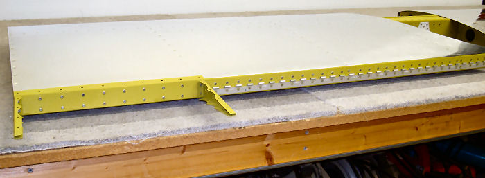
Step 01:
Cleco the HS-1215 Skin Splice Plate to the aft flanges were the
HS-1201-R & L Main Skins meet as shown in Figure 1. Step 02: Match-Drill #52 the 1/16" holes in the HS-1215 Skin Splice Plate into the aft flanges of the HS-1201-R & L Main Skins called out in Figure 1. Remove the skin splice plate, deburr holes and clear away any chips. Builder Note: See Step: 11-04-04 |
 |
|||||||||||
| NOTE: Step 3 through
Step 5 describe installation of parts on the right side of the
Stabilator Assembly, installation for parts on the left side is a mirror
of the right. Step 03: Rivet the HS-1218-R Aft Hinge to the HS1201-R Main Skin. Include the HS-1216 Aft Main Ribs when riveting the holes common to the aft hinge, main skin and aft main ribs. Include the HS-1215 Skin Splice Plate, on the inside surface of the aft flange, when riveting the holes common to the aft hinge, main skin and skin splice plate. See Figure 2. 11/23/10 |
 |
|||||||||||
|
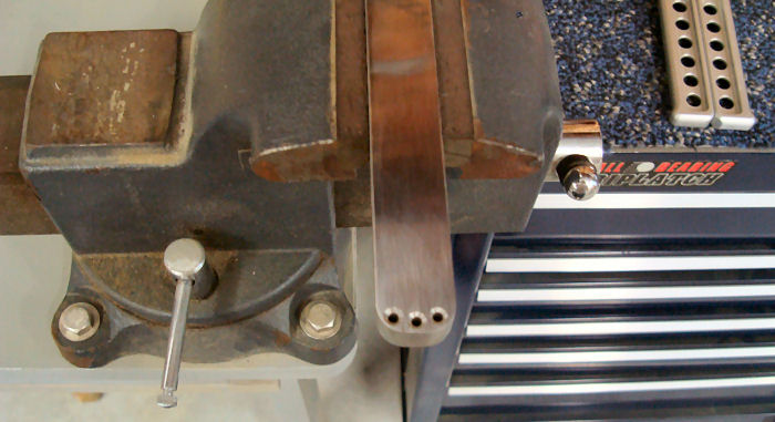
ALTERATION Builder Note: I drilled three #30 Holes in the back side of a Bucking Bar and machined with a 120° Countersink. |
 |
|||||||||||
|
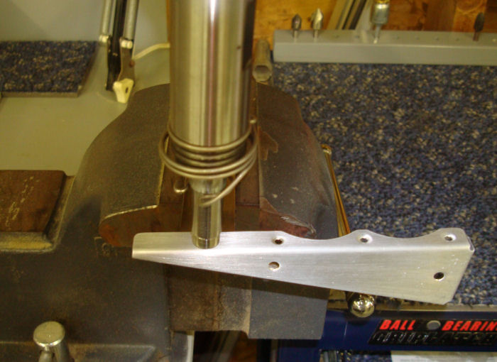
ALTERATION
Builder Note: 120°Dimple Die the 4 HS-1208 Aft Ribs 10/20/10 |
 |
|||||||||||
|
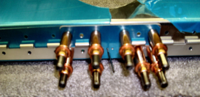
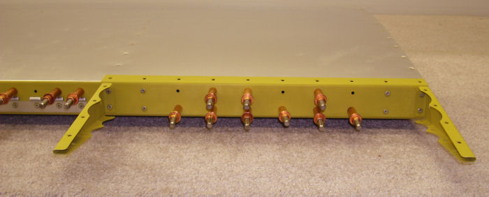
Step 04: Rivet one of the
HS-1208 Aft ribs through the HS-1201-R Main Skin to the HS-1207 Out-bd
Main Rib. Rivet one of the HS-1208 Aft Ribs through the HS-1201 Main
Skin to the HS-1206 In-bd Main Rib. Orient the ribs flanges as shown in
Figure 2. 11/23/10 |
 |
|||||||||||
|
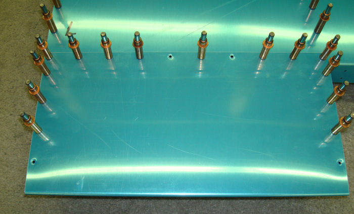
Step 05:
Rivet all of the remaining holes in the aft flanges of the HS-1201-R
Main Skin. See Figure 2. 11/23/10 |
 |
|||||||||||
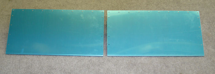
| Step 06: Separate the HS-1217 Aft Skins by removing the material
called out in Figure3. NOTE: Figure 4 illustrates the installation of the HS-1217 Aft Skin for the right side of the of the Stabilator Assembly. Installation for the aft skin on the left side is a mirror of the right |
 |
|||||||||||
|
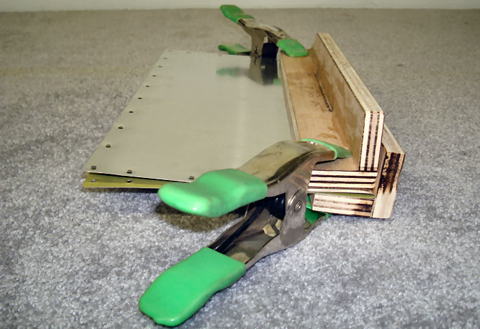
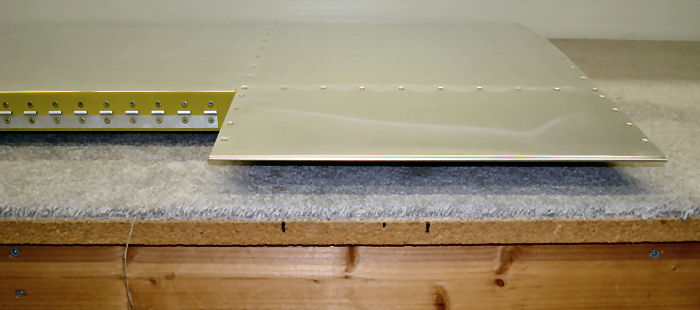
Step07: Pinch the aft edge
of the HS-1217 Aft Skin until the open end lays flat on the aft edge of
the main skin. Cleco the aft skin to the HS-1201-R Main Skin and the
HS-1208 Aft Ribs. 11/23/10 Builders Note: Pinch Just enough so the open end is about 1-1/4" 11/23/10 |
 |
|||||||||||
|
Step 08: Match-Drill #30 the holes from the
HS-1217 Aft Skin into the HS-1208 Aft Ribs called out in Figure 4. Remove the aft skin, deburr the holes and clear away any chips. |
 |
|||||||||||
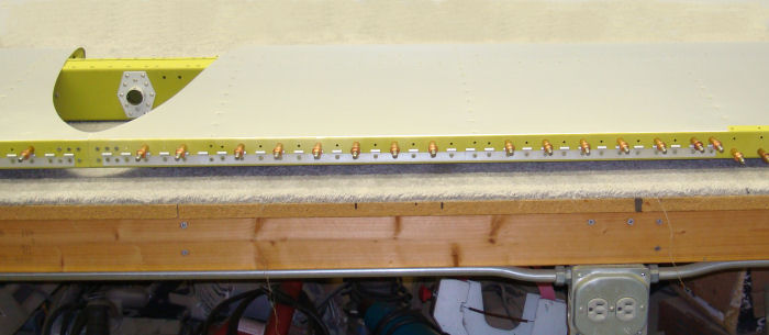
| Step 09: Rivet the
HS-1317 Aft Skin to the HS-1208 Aft Ribs and the HS-1201-R Main Skin
using rivets called out in Figure 4. 11/23/10 Alteration Rivets Used |
 |
|||||||||||
| Page 09.09 Stabilator |
|
| VERTICAL STAB | RUDDER | ANTI-SERVO TAB | STABILATOR | TAILCONE | EMP ATTACH | EMP FAIRINGS | BUILDERS LOG |
|
||||||||||
|
Disclaimer : Information contained on this Site may be out of date and /or inaccurate - Please Confirm any important data with a reliable source. |