
| Home | Empennage kit | Wing Kit | Fuselage Kit | Finish Kit | Power Plant Kit | Avionics | Paint | Interior | Home |
|
|
|||||||||||
|
|||||||||||
| CENTER SECTION | MID FUSE | LOWER FUSE | SIDE SKINS | ROLLOVER | TAIL ATTCH | SEATS | PEDALS | FUEL | FWD FUSE | BUILDERS LOG |
|
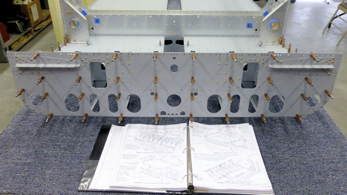
Page 21.13 Mid Fuse Ribs & Bottom Skins |
|
||||||||||||||||||||||
| Step 01: Cleco the F-1203A Bulkhead Assembly to the front flange of the F-1215-L & R Seat Ribs and to the front flange of the F-1253-L & R Seat Floor Supports. In order to align the holes in the seat floor supports with there corresponding holes in the F-1203A Bulkhead Assembly ( the holes just below the F-1203D-L & R Stub Spar Supports ), the seat floor supports need to be bent up slightly at the front of the seat floors. |
 |
||||||||||||||||||||||
|
Step 02: Rivet the F-1203A Bulkhead
Assembly to the front flange of each F-1215-L & R Seat Rib using the
rivets called out in Figure 1. Do NOT Rivet the F-1253-L & R Seat Floor
Supports at this time. Builder Note: Alteration Rivets Used: Flush and solid rivets above the floor |
 |
||||||||||||||||||||||
| Step 03: Dimple the single pair of nutplate attach holes in the forward and aft flange, and the four pair of nutplate attached holes along the inboard edge of the F-1226-L & R Seat Ramp Floors. | |||||||||||||||||||||||
| Step 04: Dimple the single #30 hole on the forward flange, and the four #30 holes along the inboard edge of the F-1226-L & R Seat Ramp Floors that are called out for flush rivets | |||||||||||||||||||||||
| Step 05: As indicated in Figure 2, final-drill to1/2" the forward 3/8" hole in the F-1226 -L & R Seat Ramp Floors. | |||||||||||||||||||||||
| Step 06: Rivet in place F-1226-L & R Seat Ramp Floors using the rivets called out in Figure 2. | |||||||||||||||||||||||
|
Step 07: Reach through the
lightening hole in one of the F-1215-L & R Seat Ribs and attach the
nutplate to the back of the F-1203A Bulkhead as shown in Figure 3. Dimple, then attach the four nutplates to the bottom of the F-1215L Seat Rib flange and the nutplate to the bottom of the F-1225-R Seat Floor using the rivets called out in the figure. Repeat this step for the left side of the fuselage. |
|||||||||||||||||||||||
| Step 08: To remove powder coating from the bolt holes in the WD-1210 Control Column ( shown in Figure 4 ), final -drill #12 all of the 3/16" holes and final-drill 1/4" all the 1/4" holes. | |||||||||||||||||||||||
| Step 09: Insert the WD-1210 Control Column through the lightening holes of the F-1215-L & R Seat Ribs as shown in Figure 4. If necessary, the F1253-R Seat Floor Support can be carefully bent down, out of the way, while inserting the control coiumn. | |||||||||||||||||||||||
|
||||||||
|
Note: This is my builders log and is not Intended to replace Vans Construction drawings |
||||||||
|
Disclaimer : Information contained on this Site may be out of date and /or inaccurate - Please Confirm any important data with a reliable source. |