
| Home | Empennage kit | Wing Kit | Fuselage Kit | Finish Kit | Power Plant Kit | Avionics | Paint | Interior | Home |
|
|
|||||||||||
|
|||||||||||
| CENTER SECTION | MID FUSE | LOWER FUSE | SIDE SKINS | ROLLOVER | TAIL ATTCH | SEATS | PEDALS | FUEL | FWD FUSE | BUILDERS LOG |
|
Page 21.10 Mid Fuse Ribs & Bottom Skins |
|
||||||||||||||||||||||
|
Step 01: Carefully deburr the edges
and holes of the F-1233A Control Column Mount Spacer and the F1233B-L &
R Control Column Mount Brackets so that the parts will fit together
tightly. 8/15/12 |
 |
||||||||||||||||||||||
|
Step 02: Machine countersink the
four holes surrounding the bearings hole in the F-123B-L & R Control
Column Mount Brackets. Machine countersink flush on the
outboard sides of both brackets for double - flush rivets. Machine
countersink the two sets of nutplate attach rivet holes in the sloped
flanges ( flush on top ). 08/16/12 |
 |
||||||||||||||||||||||
|
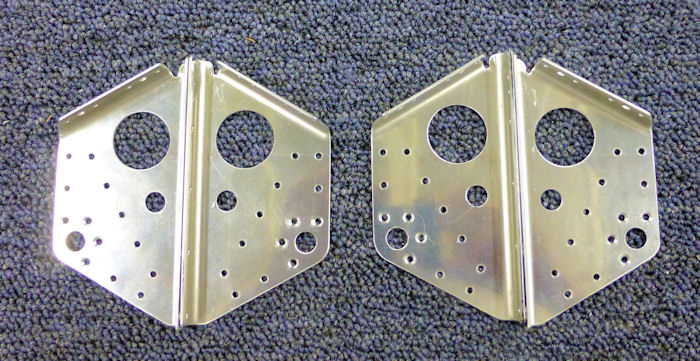
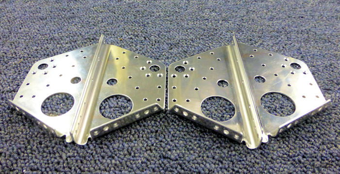
Step 03: As shown in Figure 1,
sandwich the bearing and the F-1233A Control Colum Mount Spacer between
the F-1233B-L & R Control Column Mount Brackets, then rivet the parts
together using the rivets called- out. The hole indicated in the control
column mount spacer locates the to of the part. Builder Note: Alteration Rivets Used 08/17/12 |
 |
||||||||||||||||||||||
|
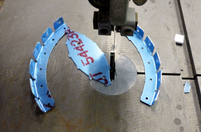
Step 04: Separate the F-1203B
Bulkhead Flange by Removing the hatched area shown in Figure 2. 08/15/12 |
 |
||||||||||||||||||||||
|
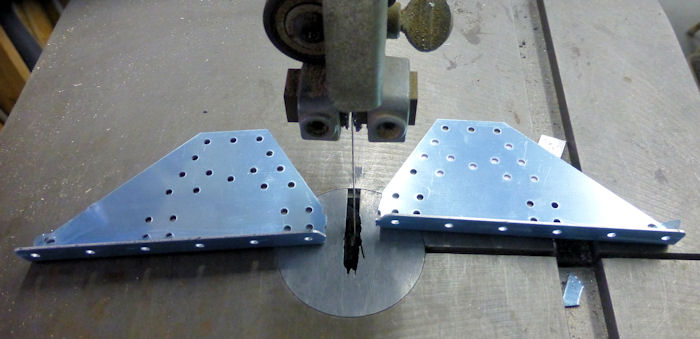
Step 05: Separate the F-1203D Stub
Spar Receptacle Support by removing the material shown in Figure 3. 8/15/12 |
 |
||||||||||||||||||||||
|
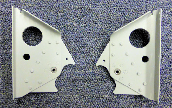
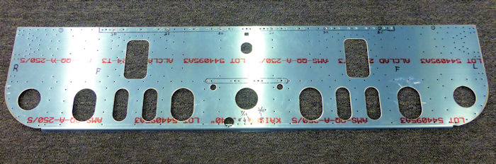
Step 06: Figure 4 depicts the
forward forward face of the F1203A Bulkhead. The bottom flange is bent
back, into the page. Machine countersink all of the #40 nutplate attach
rivet holes and the six #30 holes in the areas indicated. Machine
countersink the #30 holes 120° 08/14/12 |
 |
||||||||||||||||||||||
|
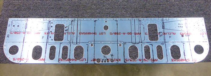
Step 07: As shown in Detail A,
drill the four 1/8" holes to the sizes indicated and remove the hatched
area from the 7/8" hole to make it completely circular. The hatched area
can be removed by snipping between the small holes using dikes / wire
cutters, then finishing with a round file. 08/16/12 |
 |
||||||||||||||||||||||
| Step 08: As shown in Figure 5, rivet the F1203B-L Bulkhead Flange to the left, aft side of the F-1203A Bulkhead using the rivets called out, | |||||||||||||||||||||||
| Step 08B: Repeat Step: 08 for the right side of the bulkhead using the F-1203B-R Bulkhead Flange, | |||||||||||||||||||||||
|
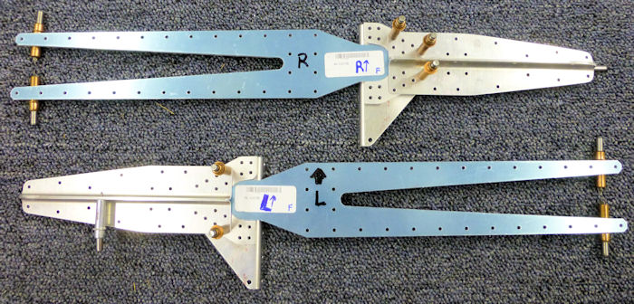
Step 09: File the curved recess of both F-1203C Stub Spar
Receptacles ( the bevel locates the top of the part, see Figure 5 ) to
closely fit the rounded mating ends of the Stub Spar Assemblies of both
wings. Once filed, mark the parts so that will be assembled on the side
they were fitted to . Builder Note: Stub Spares orderd separately to accomplish this step. 08/16/12 |
 |
||||||||||||||||||||||
|
Step 10: Cleco the F-1203C Stub
Spar Receptacle and the F-120D-L Stub Spar Receptacle Support to the F1203A Bulkhead as shown in Figure 5. Rivet the parts together using the two rivets called-out. Final-Drill #30 any holes too tight to accept to accept a rivet. Builder Note: Install Only Two Rivets This Step |
|||||||||||||||||||||||
|
Step 10B:
Repeat step 10 for the right side of the bulkhead using the remaining
F-1203C Stub Spar Receptacle and the F103D-R Stub Spar Receptacle
Support. Builder Note: Install Only Two Rivets This Step |
|||||||||||||||||||||||
|
|||||||||||||||||||||||
|
|||||||||||||||||||||||
|
Disclaimer : Information contained on this Site may be out of date and /or inaccurate - Please Confirm any important data with a reliable source. |
|||||||||||||||||||||||