Page 21.15
Mid Fuse Ribs
& Bottom Skins |
|
|
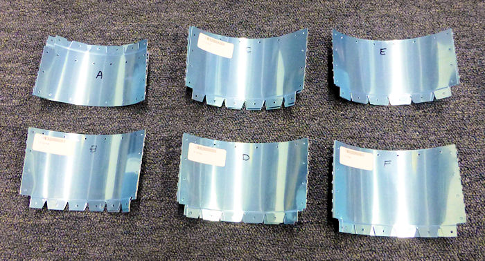
Step 01: Separate the F-1275A, B'
C, D, E and F Fuselage Corner Skins along the center perforations. The
notches in different tabs, shown in Figure 1, can be used to
differentiate the parts. |
 |
|
Step 02: Turn the fuselage
upside-down on a pair of saw horses. As shown in Figure 2, cleco the
F-1275-R Fuselage Corner Skin to the F-1253-R Seat Floor Support, the
F1215-R Seat Rib and the F-1204P-R Skin Attach Flange. Then, one after
the other, cleco in place the F-1275E-R, D-R, C-R, B-R and A-R Fuselage
Corner Skins as shown. |
|
|
Step 03: Using the rivets called
out in Figure 2, rivet the F1275A B, C, D, E and F right side Fuselage
Corner Skins to each other. Rivet the F-1275A-R to the F-1204P-R Skin
Attach Flange ( except for the four holes indicated ). DO NOT RIVET the
fuselage corner skins to the F-1253-R Seat Floor Support or to the
F-1215-R Seat Rib. |
|
|
Step 04: Repeat Steps 2 and 3 for
the left side of the fuselage. |
|
|
Step 05: Cleco the F1274-R Fuselage Corner Skin to the F-1202F
Bulkhead, the F-1212-R Step Rib and the F-1275A-R Fuselage Corner Skin. |
|
|
Step 06: Except for the two holes
indicated in Figure 3, rivet the F-1274-R Fuselage Corner Skin to the
F-1275A-R Fuselage Corner Skin. Do Not Rivet to the F1212R Step Rib or
to the F1202F Bulkhead. |
|
|
Step 07: Repeat Steps 5 and 6 for
the left side of the fuselage. |
|
|
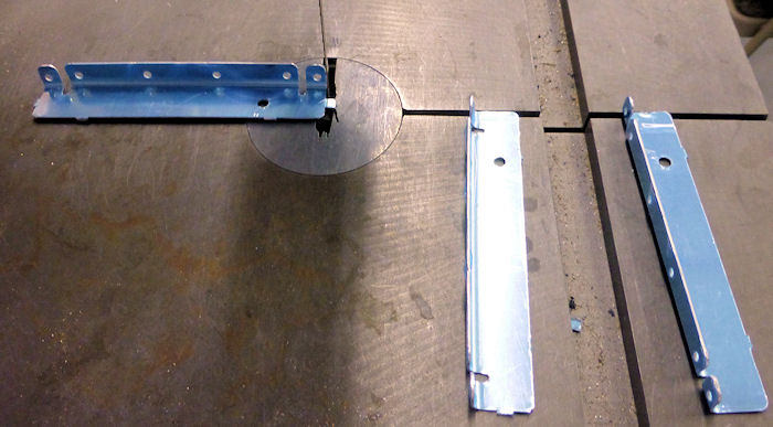
Step 08: Separate the F-1204Z
Bottom Stiffeners by removing the hatched areas shown in Figure 4. |
 |
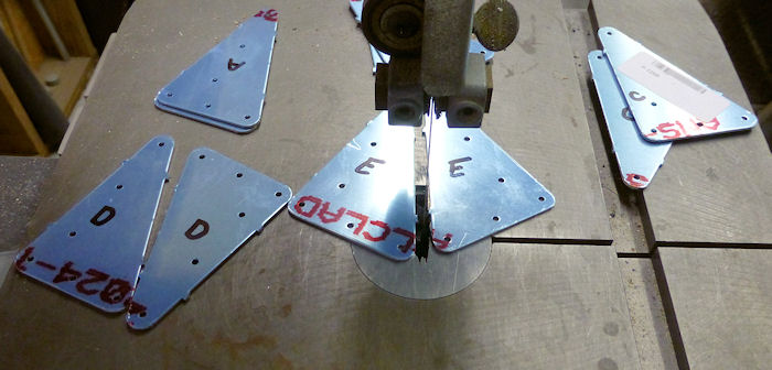
Step 09: Mark each part, then
separate the F-1268A, B, C, D & E Doublers shown in Figure 5.
|
 |
| |
|


