
| Home | Empennage kit | Wing Kit | Fuselage Kit | Finish Kit | Power Plant Kit | Avionics | Paint | Interior | Home |
 |
|||||||||||
|
|||||||||||
| CENTER SECTION | MID FUSE | LOWER FUSE | SIDE SKINS | ROLLOVER | TAIL ATTCH | SEATS | PEDALS | FUEL | FWD FUSE | BUILDERS LOG |
|
Page 21.17 Mid Fuse Ribs & Bottom Skins |
|
||||||||||||||||||||||
|
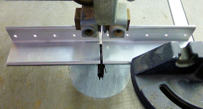
Step 01: Separate the F-1236 Step
Attach Angles by removing the hatched areas shown in Figure 1. 09/09/12 |
 |
||||||||||||||||||||||
|
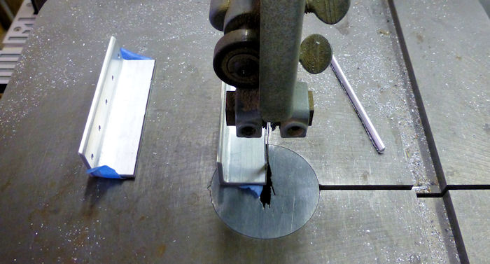
Step 02: AS shown in Figure 2, make
the F-1236B-L & R Outbd Step Attach Angles by trimming the flanges of
the two angles separated in Step 1. ( At this point these two parts are
identical, but will become left and right once they are drilled in a
later step. The two, remaining, untrimmed angles separated in Step 1 are designated F-1236A-L & R Inbd Step Attached Angles. 09/09/12 |
 |
||||||||||||||||||||||
|
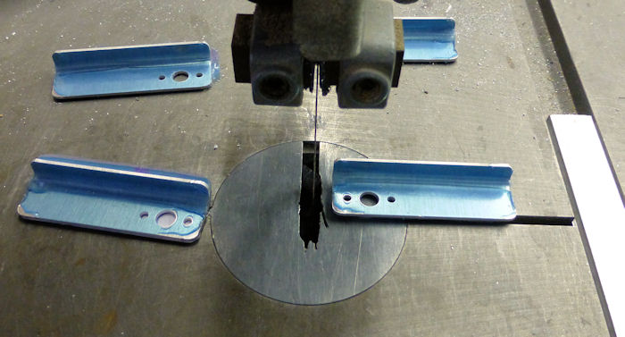
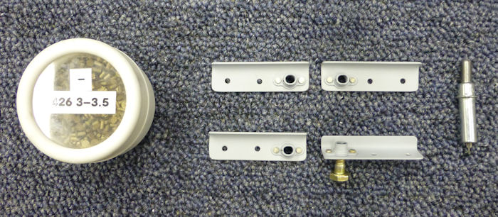
Step 03: Separate The F-1251 nutplate Bracket into individual
parts by removing the hatched areas shown in Figure 3. 09/09/12 |
 |
||||||||||||||||||||||
|
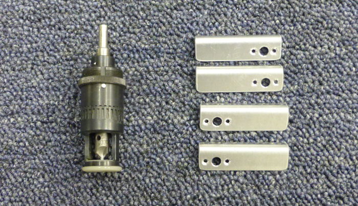
Step 04: Machine countersink the
F-1251-L & R Nutplate Brackets for the nutplate attach rivets called out
in Figure 3, Builder Note: Deburr, scuff ,clean then Prime 09/09/12 |
 |
||||||||||||||||||||||
|
Step 04B: then rivet the nutplates
in place. 09/12/12 |
 |
||||||||||||||||||||||
|
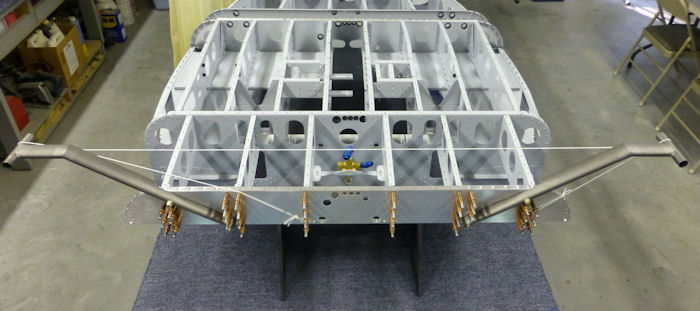
Step 05: Cleco the 1236A-L Inbd
Step Attach Angle to the F-1212-R Step Rib and the the F-1236B-L Outbd
Step Attach Angle to the F-1212-L Step Rib as shown in Figure 4, then
match drill #30 the indicated holes of the F-1202F Bulkhead in to the
step attach angles. Cleco the holes, then repeat this step for the right side of the fuselage. |
|||||||||||||||||||||||
| Step 06: Final-Drill 1/4" the hole in the F-1202F Bulkhead and F-1236B-L Outbd Step Attach Angle that is indicated in Figure 5. | |||||||||||||||||||||||
| Step 07: Temporarily bolt the WD-1233-L Step to the F1202F Bulkhead and F_1236B-L Outbd Step attach Angle. | |||||||||||||||||||||||
| Step 08: Make the pad of the WD-1233-L horizontal, however, the inbd, top corner of the step is to remain even with or below the beginning of the radius of the F1202F Bulkhead. See Figure 5. Once the step is positioned, match-drill 1/4" the inboard hole of the step into the bulkhead and F-1236A-L inbd Step Attach Angle. Remove the step. | |||||||||||||||||||||||
| Step 09: Seal the opening ( see Figure 5 ) in the WD-1233L Step with fuel tank sealant. | |||||||||||||||||||||||
|
Step 10: Repeat Steps 6 through 9
for the right side of the fuselage using the WD-1233-R Step. Builder Note: adjust step until string across the top of the steps is parallel to the F-1202F Bulkhead. |
 |
||||||||||||||||||||||
|
||||||||
|
Note: This is my builders log and is not Intended to replace Vans Construction drawings |
||||||||
|
Disclaimer : Information contained on this Site may be out of date and /or inaccurate - Please Confirm any important data with a reliable source. |