
| Home | Empennage kit | Wing Kit | Fuselage Kit | Finish Kit | Power Plant Kit | Avionics | Paint | Interior | Home |
|
|
|||||||||||
|
|||||||||||
| WING ATTACH | WIRING | FLIGHT CONTROL | MISCELLANEA | CANOPY | LANDING GEAR | FUEL | COWLING | OPTION'S | BUILDERS LOG |
| Page 32.14: FLIGHT CONTROLS |
|
||||||||||||||||||||||
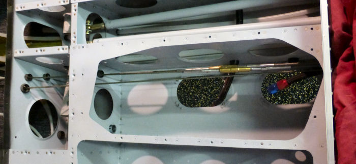
| Step 01:
Route the Aft Stabilator Cables forward through the holes in the
F-1207B and F1206A Bulkheads; see Figure 1. The cable from the top
Stabilator horn passes through the top hole. Builder Note: These cables were installed before header tank modification to the baggage floor was cutout. The Stabilator was removed for the vinyl install. The lock clips were install after the Stabilator was installed the last time. 06/10/18 |
 |
||||||||||||||||||||||
| Step 02: Route the Forward Stabilator Cables aft through the holes in the F-120A & D Bulkheads; see Figure 1. The cable from the right pulley passes through the upper hole. |
Once the
proper tension is achieved, and no more than three threads are exposed
from the ends of the barrels, align the V-notch in the ends of the
barrel with the groove in the cable ends and then insert the lock clips
as shown in Figure 3. the hook end of the lock clips are inserted into
the hole in the center of the barrel and must be completely
pressed in until the hook springs open inside the barrel. |
||||||||||||||||||||||
| Page 32.14: |
|
|
|
||||||||||
|
Disclaimer : Information contained on this Site may be out of date and /or inaccurate - Please Confirm any important data with a reliable source. |