|
Page 32.11: FLIGHT
CONTROLS |
|
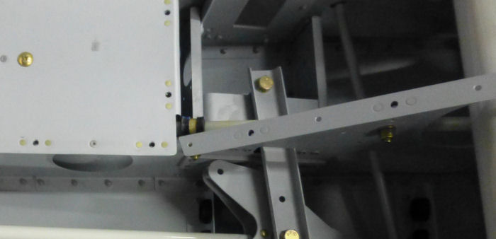
Step 01:
Rout the spade end ( not the fork end ) of the F-1239 Rudder Cables
along with the plastic sleeve on both rudder cables, forward through the
SB750-10 snap bushings in the F-1207B, F-1206A , F-1204D and A Bulkheads
( see Page 21-14 Figure 3 and Page 21-19 Figure 3 ). Leave the plastic
sleeves at the location shown in Figure 1, then continue routing the
cable ends through the two 9/16" holes in the F-1203A Bulkhead and the
two upper SB750-10 snap bushings in the F-1202F Bulkhead.
Step
02: Using the hardware shown in Figure 1, secure the plastic sleeve on
both F-1239 Rudder Cables as shown in Figure1.
12/29/13 |
 |
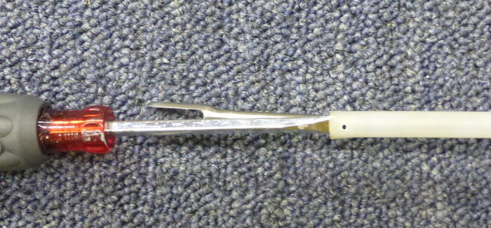
Step 03: Drill a #40
hole approximately 3/16 of an inch from the aft end of the 10 inch long
plastic sleeve that is on both F-1239 Rudder Cables as shown in Figure
2.
Builder Note: I used a screwdriver to protect the cable while
drilling the #40 drill.
12/25/13
|
 |
| Step 04: Pull the 10
inch long plastic sleeves over the shaft of the fork ends of the F-1239
Rudder Cables and safety wire them to the fork ends as shown in Figure
2. |
|
| Step 05: Use the string
that was routed through the tailcone in Section 10 to pull the F-1239
Rudder Cables through the Snap Bushing Brackets and out the F-1211
Bulkhead. |
|
| Step 06: Temporarily
attach one F-1258 Rudder Cable Link to the fork end of both F-1239
Rudder Cables as shown in Figure 3. |
|
| Step 07:Temporarily
attach the spade ends of the F-1239 Rudder Cables to the horns on the
WD-1206 Rudder Pedals as shown in Figure 4. ( Secure the aft end of the
rudder cables with a wire or string so that they are not pulled back
through the F-1211 Bulkhead ). |
|
| Step 08: Using the wood
from the crating that the kit was shipped in, cut and nail together the
Rudder Pedal Rigging Stop as shown in Figure 5. |
|
| |
|
|
Page 32.11: FLIGHT
CONTROLS |
|
