
| Home | Empennage kit | Wing Kit | Fuselage Kit | Finish Kit | Power Plant Kit | Avionics | Paint | Interior | Home |
 |
|||||||||||
|
|||||||||||
| Home | Alterations | Vendors | Builders Log | Home |
| Alteration 10.01 Seat Brace |
|
|||||||||||
| Page 10.01 | NOTE: Any alteration will require it to be registered as Experimental-Amateur Built E-AB | |||||||||||
|
Parts 2 - 1/4 X 2 X 2.5 X 3" angles |
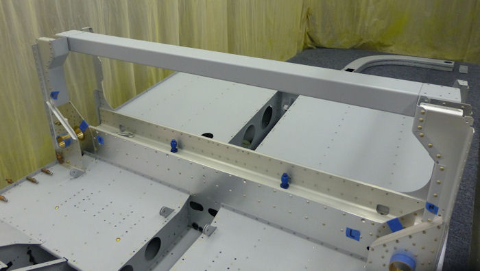
This Alteration is to make the Seat brace removable ( MID FUSE BRACE ) |
|||||||||||
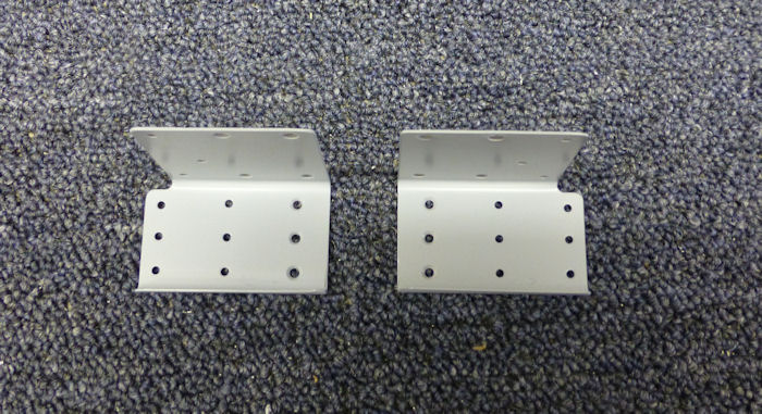
| Step 01: Cut square 2
7/8" off
the ends of the F-1205A Mid Fuse Brace. 01/05/13 |
 |
|||||||||||
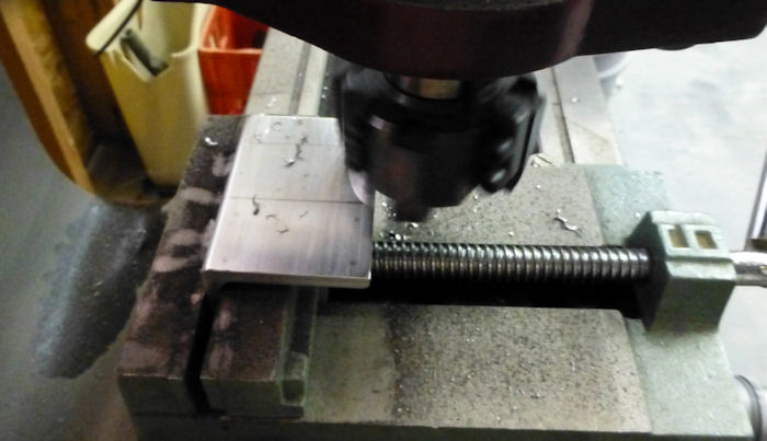
| Step 02: Make two
angles to add to the ends of the F-1205A. See Step 04 12/15/12 |
 |
|||||||||||
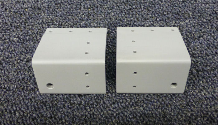
| Step 03: Match
Drill #30 7 holes in each angle. 01/06/13 |
 |
|||||||||||
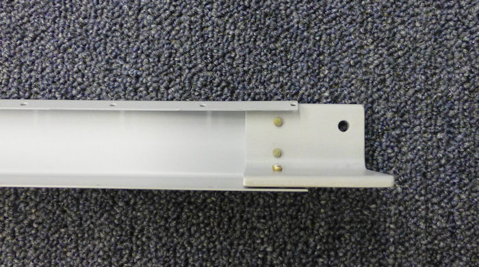
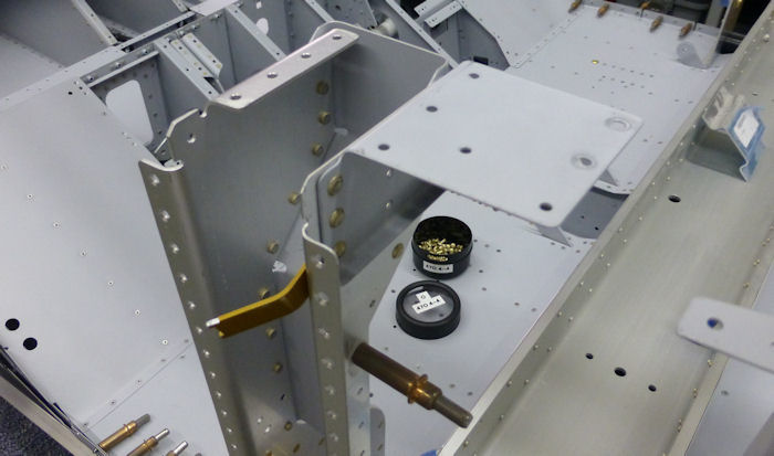
| Step 04: Rivet the two
new angles to the F-1205A Mid Fuse Brace. Note The Angle projects 1.5" at each end. 01/06/13 |
 |
|||||||||||
| Step 05: Rivet The cut
off ends of the F-1205A Mid Fuse Brace to the F-1024B-L and R Aft
bulkhead sides. 01/05/13 |
 |
|||||||||||
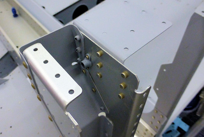
| Step 06: Add a 1/4 - 28
nut plate. 01/12/13 |
 |
|||||||||||
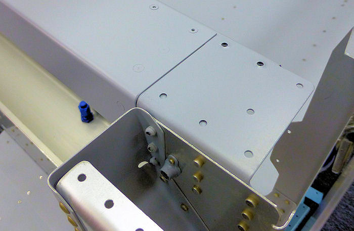
| Step 07: Dimple the cut
off ends of the F-1205A Mid Fuse Brace as required to allow the new
angle to be flush with the bottom of the end plate.
01/12/13 |
 |
|||||||||||
|
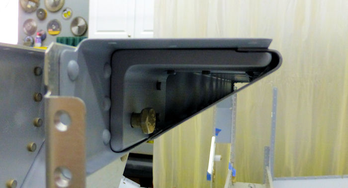
Step 08: End view Note: The reason for the milled notch in Step: 02 01/12/13 |
 |
|||||||||||
Step 09: Deburr, scuff and prime the F-1205C. 01/06/13 |
 |
|||||||||||
| Step 10: Attach the
F-1205C to the Modified F-1205A. Note: This is 39.375" long at the top and 36.375" at the bottom. 01/06/13 |
 |
|||||||||||
| Step 11: Test fit the
new removable Mid Fuse Brace. Note: The 3/32" gap at each end of the F-1205A from the saw cuts from Step: 01 01/12/13 |
 |
|||||||||||
| To see Vans drawing | Click - PDF Page 23.03 - to open in new window | |||||||||||
| Page 10.01 |
|
|
|
||||||||||
|
Disclaimer : Information contained on this Site may be out of date and /or inaccurate - Please Confirm any important data with a reliable source. |